
What causes a heat sink to fail in high‐temperature environments?
Leading paragraph:
Picture a heat sink in a furnace‐like place. The metal warps, the joints loosen, the cooling fails and the whole module overheats.
Featured paragraph:
A heat sink can fail in high‐temperature environments due to poor thermal interface, material creep, oxidation, mechanical stress and excessive ambient heat — resulting in higher junction temperature and eventual component degradation.
Transition paragraph:
In the following sections I’ll explore what “failure” really means for a heat sink, how extreme heat affects materials, how you can prevent failure in harsh conditions, and what new materials are showing up to handle high temperatures better.
What is considered heat sink failure?
Leading paragraph:
You may ask: what makes a heat sink “fail”? It’s more than just “getting hot”.
Featured paragraph:
Heat sink failure means the sink no longer maintains acceptable thermal performance — i.e., the thermal resistance rises, junction temperature goes above specification, causing the device to under‑perform, degrade or fail.
Dive deeper paragraph:
From my experience with industrial lighting modules and aluminium extrusions, I’ve seen several manifestations of heat sink failure. Failure is not just “the sink gets hot” — it’s when the thermal system no longer keeps the LED or driver within safe temperature limits. For example:
Types of failure
- The thermal interface material (TIM) degrades or dries out, so the conduction path worsens.
- The heat sink mounting loosens, contact resistance increases, or there is a gap or air pocket.
- The material itself suffers creep or deformation under high temperature and continuous load, so fins bend or warp.
- Oxidation or corrosion builds up on surfaces, reducing thermal conductivity or airflow.
- The heat sink size, airflow path or orientation is inadequate, leading to junction temperature rising above safe limits.
What’s the threshold?
When the junction temperature (Tj) of the device rises above its rated maximum for prolonged time, the lifetime falls dramatically. When you see increasing thermal resistance (°C/W), reduced light output (for LEDs), colour shift, or early driver failure — you are in failure territory. One guide mentions “10 signs your heat sink needs replacement” including overheating, discoloration, deformation, repeated thermal shutdown.
Why this matters
In a lighting module containing LED + driver + aluminium extrusion, if the heat sink fails, the LED lumen depreciation accelerates, colour changes, drivers may fail, warranty claims increase. For B2B manufacturing you want to avoid that.
Here are two true/false checks:
Heat sink failure only means physical breakage of the fins.False
Failure includes thermal performance loss due to interface, material changes, not just physical fracture.
When the junction temperature of the device rises above spec because the heat sink no longer dissipates heat effectively, the heat sink is effectively failing.True
Yes—elevated Tj due to insufficient heat dissipation indicates heat sink failure.
What are the effects of extreme heat on materials?
Leading paragraph:
Materials under extreme heat do various bad things — they bend, oxidize, creep, lose strength or change conductivity.
Featured paragraph:
Extreme heat can cause materials to creep, oxidize, lose thermal conductivity, suffer fatigue and corrosion — all of which reduce the effectiveness of a heat sink and can lead to failure.
Dive deeper paragraph:
Let’s break this down into how different degradation mechanisms apply to heat sink materials (commonly aluminium, copper, alloys) and interface components.
Creep and deformation
When a metal is under stress at elevated temperature (for example, gravity, mounting bolts, thermal expansion), over time it slowly deforms — this is creep. If fins warp, mounting loosens, the contact with the LED module worsens. Superalloy literature emphasises this effect in extreme temps.
Oxidation and corrosion
At high temperatures in air (or in humid/contaminated atmospheres), surfaces oxidise. Oxide layers have lower thermal conductivity and may act as insulating layers between the heat sink and air or between module and sink. This increases resistance. Also corrosion can degrade structural integrity.
Thermal fatigue and expansion mismatch
Repeated thermal cycling (heating and cooling) causes expansion and contraction. When different materials are joined (e.g., aluminium sink + soldered copper base + plastic mount), the mismatch can lead to cracks, delamination, loosening of joints or TIM degradation. This degrades the thermal path.
Loss of thermal conductivity or mechanical strength
Metals at high temperatures sometimes suffer microstructural changes (grain growth, phase changes) which reduce strength or conductivity. Polymers, adhesives, thermal pastes may degrade, dry out or char, raising interface resistance.
Reduced airflow or increased ambient
In high ambient temperature environments, the delta temperature (sink‑to‑air) shrinks. The sink must dissipate the same heat into a hotter air mass, reducing margin. If airflow is restricted (dust, debris, enclosure) then heat builds up further.
Example applications
In outdoor lighting in Middle East or Africa where ambient may rise to 50 °C or more, the heat sink must handle worst case offset. If material limts are exceeded then you see early lumen drop or LED failure.
Summary table of effects
| Degradation Mechanism | Materials Impacted | Consequence on Heat Sink Performance |
|---|---|---|
| Creep / deformation | Metal fins, mounting brackets | Warping, loosening → worse contact |
| Oxidation / corrosion | Metallic surfaces, TIM layers | Reduced conduction, higher thermal resistance |
| Thermal fatigue / cycling | Joints, solder, TIM, interfaces | Cracks, delamination, increased interface resistance |
| Material property change | All sink/base materials | Lower conductivity, strength, thermal path worsens |
| High ambient / low airflow | Entire system | Reduced temperature differential → higher Tj |
Here are two true/false statements:
Repeated thermal cycling in a high temperature application cannot affect the joint between module and heat sink.False
Thermal cycling causes expansion/ contraction which degrades joints and interfaces over time.
Oxidation of heat sink surfaces in harsh environment can reduce its effective thermal conduction path and lead to higher operating temperature.True
Yes—the oxidised layer adds thermal resistance and degrades performance.
How can I prevent heat sink failure in harsh conditions?

Leading paragraph:
Preventing failure in harsh conditions requires thoughtful design, material choice, installation and maintenance.
Featured paragraph:
You can prevent heat sink failure by ensuring proper thermal interface, choosing corrosion/creep‑resistant materials, designing for worst‑case ambient/airflow, maintaining clean surfaces and verifying via testing or monitoring.
Dive deeper paragraph:
Given your business in aluminium extrusions and lighting modules for export, you know harsh conditions (high ambient, outdoor, desert, enclosed fixtures) are real. Here’s how I’d approach prevention.
Step 1: Design for worst case
Define the worst ambient temperature, airflow (natural vs forced), enclosure insulation, driving current. Use this to calculate required thermal resistance, margin. Over‑specify rather than just meet nominal. Provide a safety factor (e.g., 1.5×). Make sure the extrusion or sink you use can maintain junction temperature below Tj‑max under worst case.
Step 2: Choose suitable materials and finishes
Pick metals that resist creep and corrosion. For example, in extremely hot ambient and high stress, you might choose alloys with higher creep resistance (rather than plain aluminium). Use surface treatments to resist oxidation (anodising, protective coatings). Ensure TIM is high quality and rated for elevated temperature (some thermal pastes degrade at high temp or after many cycles).
Provide good contact: flatness, proper mounting torque, minimal air gaps. Use high‑conductivity TIM, ensure bolt pattern distributes pressure.
Step 3: Ensure good mounting and thermal interface
Mechanical design: secure mounting to maintain contact under vibration/thermal cycling. Use screws, retention features, avoid adhesives only. Interface: apply correct amount of TIM, ensure no air bubbles, ensure direct contact. Avoid materials that insulate or degrade over time (foam, low‑grade glue).
Consider adding a thermal spreader or intermediate plate if the heat sink is not directly against the heat source.
Step 4: Allow airflow / convection / ventilation
Even the best heat sink will fail if air can’t move. Design the fixture/assembly so air can enter/exit, fin spacing is correct, orientation is optimal (for natural convection fins may be vertical). Prevent clogging: design for dust, sand, outdoor exposure. Use protective meshes or coatings.
If natural convection is insufficient in high ambient, consider forced airflow or heat pipe/active cooling.
Step 5: Environmental protection & maintenance
In outdoor or desert conditions: provide corrosion‑resistant coatings, seal joints to prevent ingress of dust/ moisture, inspect/clean regularly. Provide proper IP rating or variety of materials for humidity/salt/sand.
Ensure maintenance procedures: cleaning, checking mounting torque, verifying thermal paste condition, measuring temperature run‑up.
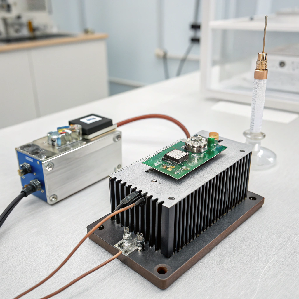
Step 6: Monitoring and verification
Use temperature sensors in prototypes and production to monitor real-world performance. Validate your designs under worst case conditions (heat chamber tests, thermal cycling, vibration). For large orders ensure supplier quality control.
Track failures and field data: if you see elevated case temperatures, rising driver temps, or lower output, revisit thermal design.
Quick prevention checklist
- Calculate worst‑case ambient + airflow + module power.
- Choose aluminium or alloy with enough thermal margin; finish surfaces for corrosion/oxidation resistance.
- Use high‑quality TIM and proper mounting.
- Provide adequate fin spacing, orientation, ventilation.
- Seal and protect from dust/ moisture, clean regularly.
- Test in heat chamber, monitor temps in the field.
Here are two statement checks for this section:
Using standard aluminium extrusion with no consideration of ambient or airflow is acceptable for all outdoor lighting heat sink applications.False
Outdoor/high‑ambient applications need extra margin, material/fin design and airflow consideration.
Implementing high‑quality thermal interface material and ensuring solid contact between module and heat sink can significantly reduce risk of failure in harsh conditions.True
Yes—a proper interface reduces thermal resistance, lowers junction temperature and improves reliability.
What are the new materials for high‐temperature performance?
Leading paragraph:
Materials science is advancing and new heat‑sink / thermal‑management materials are emerging that perform better under high temperature and high power density.
Featured paragraph:
New materials for high‑temperature performance include graphite foam/graphite composites, pyrolytic graphite laminates, superalloys, advanced ceramics and phase‐change/porous materials that handle higher temps, resist creep and have very high thermal conductivity.
Dive deeper paragraph:
Since you’re in aluminium extrusion manufacturing and supplying lighting/industrial modules worldwide, keeping an eye on these material advances gives you an edge. Here are some of the notable trends:
Graphite foam and composite heat sinks
Studies show graphite foam (engineered foam) offers very high in‑plane thermal conductivity and weight advantage compared to metal. One investigation compared copper, aluminium and graphite foam for identical geometry. The advanced carbon‑based materials allow good heat spreading.
This means you could consider composite inserts or hybrid metal+graphite structures for modules needing higher density or lower weight.
Pyrolytic graphite laminates (APG/TPG)
Materials like annealed pyrolytic graphite (APG) have extremely high in‑plane thermal conductivity (e.g., ~1700 W/mK) and remain stable across wide temperature ranges. They are typically encapsulated in metals for mechanical strength. These are used in aerospace electronics but trickle into high‑end lighting/thermal modules.
For your lighting extrusions, integrating a graphite laminate or aluminium/graphite hybrid to absorb and spread heat rapidly can be a differentiator.
Superalloys and high temperature metals
In really harsh environments (say > 200‑300 °C continuous), materials like Inconel (nickel‑chromium superalloy) or other superalloys or ceramics are used. They resist creep, maintain strength, resist oxidation and perform under high stress. While typically cost‑high for standard lighting, for premium/high‑power or extreme outdoor modules they may be relevant.
Your extrusion line may focus on aluminium alloys but you might keep a variant offering higher temperature alloy or hybrid for extreme applications.
Phase‐change and porous structures
Recent research shows structured porous materials combined with phase‑change materials (PCM) enhance thermal performance by storing/releasing heat and reducing temperature peaks. This is more for transient/high‑power shock cooling than steady state, but point is the material world is moving beyond just metal fins.
For example, a 2025 paper on “Thermal performance enhancement in PCM heat sinks” shows benefits of porous materials in high temps.
Advanced ceramics/metal‐matrix composites
Ceramic materials like aluminium nitride (AlN), silicon carbide (SiC) and boron nitride (BN) have high thermal conductivity and excellent high‑temperature stability. One study shows high thermal conductivity wafer‐scale cubic SiC crystals over 500 W/m·K at room temperature and stable at higher temps.
For your aluminium profiles you might not shift entirely to ceramic but you could incorporate inserts or coatings with these high‑thermal‑conductivity materials.
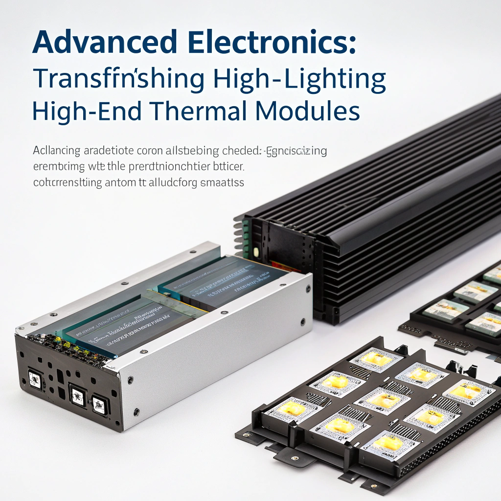
Market and manufacturing implications
For your B2B supply of aluminium profiles to lighting companies, offering “enhanced thermal profile” variants that incorporate hybrid materials (graphite insert, ceramic composite, enhanced alloy) can allow you to cater to high‐temperature, high‐power, outdoor or industrial modules that command higher margin.
You should also watch cost trade‑offs, manufacturability (extrusion, machining, assembly), coating compatibility and recyclability.
Here are two statement checks:
Thermally conductive plastics have completely replaced aluminium and copper as the dominant heat‑sink material in high‑temperature LED lighting applications.False
While there are advances in plastics and composites, aluminium and copper (and advanced composites) remain dominant especially for high‑temperature and structural applications.
Pyrolytic graphite laminates (e.g., APG) offer ultra‑high thermal conductivity and are being used in high‑performance thermal management systems.True
Yes—APG has very high in‑plane conductivity and is used in advanced cooling/spreading applications.
Conclusion
In harsh, high‑temperature environments, reliable heat sink performance is critical. Failure happens when materials, interfaces or design don’t handle the load. By understanding how materials degrade, designing for worst case, selecting better materials and keeping up with new thermal‑management advances, you can protect your lighting modules and deliver long‑term value to clients.


