


Can a single heat sink cool multiple power components safely?
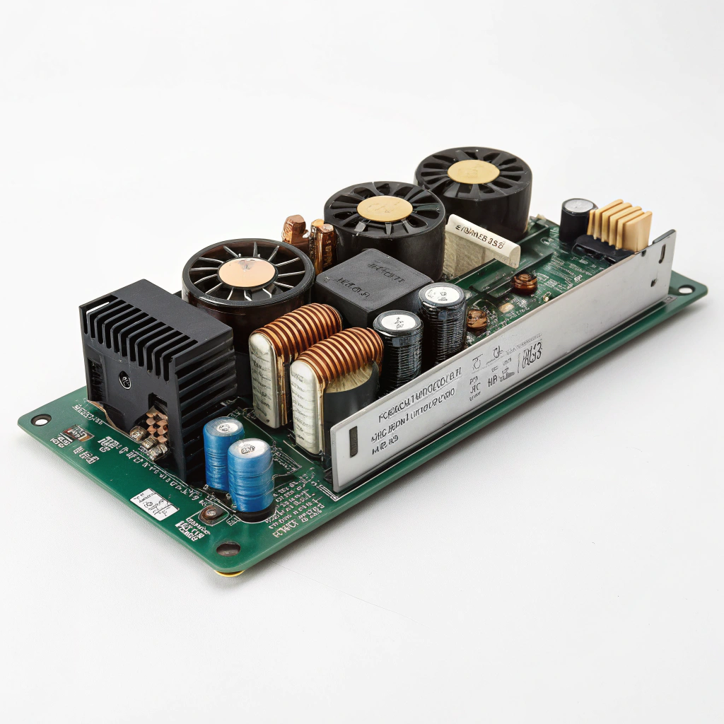
Have you ever worried that one power board with multiple hot parts might burn out because the cooling is all wrong?
Yes — a single heat sink can cool multiple power components safely — if the thermal path, power budget, electrical isolation, and layout are designed properly.
In the rest of this article I’ll walk you through what “multi‑component thermal management” means, why shared heat sinks bring benefits, how you can go about designing one, and what modular cooling trends to watch for. Let’s dive in.
What is multi‑component thermal management?
Imagine you have three transistors, a diode bridge and a regulator all on one board. They all generate heat.
Multi‑component thermal management means managing the heat from several devices together, designing how their individual thermal loads, heat flow paths and cooling infrastructure interact.
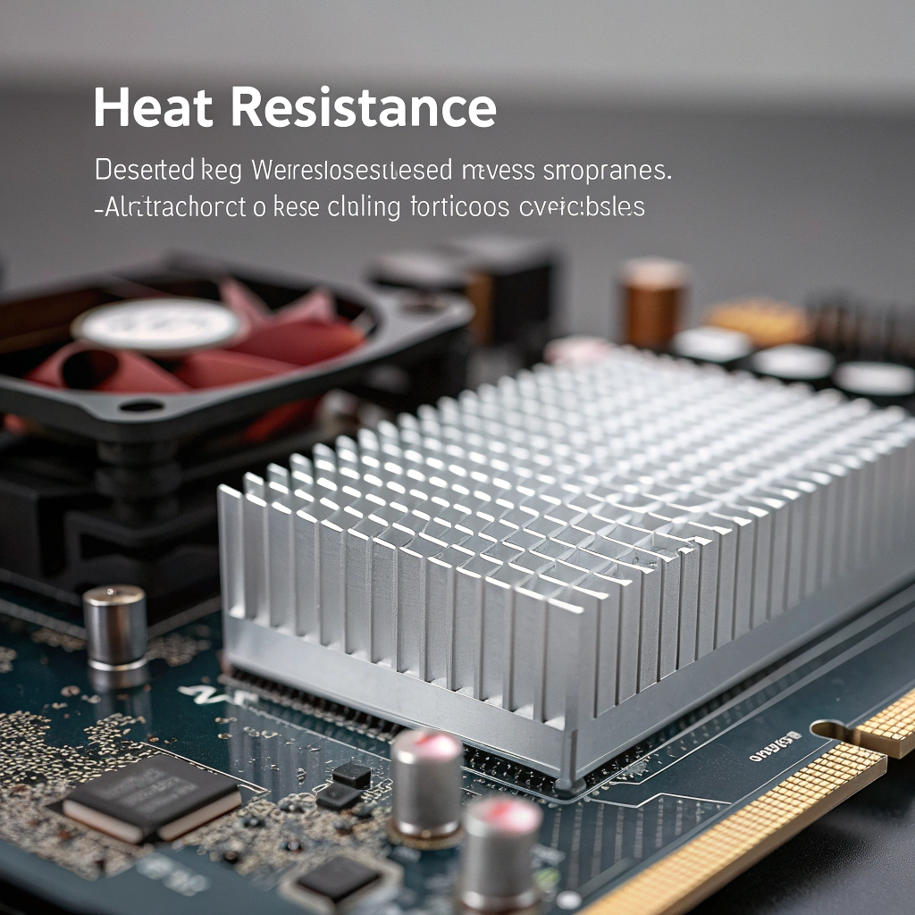
When I say “multi‑component thermal management”, I’m referring to a scenario where more than one heat‑generating component is mounted on the same board or assembly, and their cooling must be designed collectively rather than each individually. This concept raises several key challenges and opportunities:
Key aspects to consider
- Heat sources: Each component (MOSFET, IGBT, diode, regulator) has its own power dissipation curve. The total heat to be managed is the sum of all the individual devices (under worst‑case or typical conditions).
- Thermal coupling: When multiple components share a heat sink or a common thermal base, the heat from one device can raise the local temperature of the sink, which in turn affects the other devices.
- Electrical isolation: Many power devices have tabs or mounting flanges that are electrically active. If you mount multiple devices on a shared heat sink, you must check whether their mounting tabs are tied to different potentials. If so, you might need isolation (like a mica pad or ceramic insulator) which adds thermal resistance.
- Thermal path and sink sizing: You must compute the required thermal resistance of the sink from the combined heat dissipation, the maximum allowable device‑case or device‑junction temperature, ambient conditions, and air/ambient convection.
- Placement and layout: Where on the heat sink you place devices matters. If devices are far apart, the sink may not spread heat well, or mechanical stresses (differential expansion) may occur.
- Reliability and thermal interactions: If one device suddenly steps up in dissipation (say due to load change or fault), the shared sink must accommodate not only steady state but transient loads. Also thermal runaway in one device might impact neighbours if the sink cannot isolate or spread heat sufficiently.
In short, multi‑component thermal management is about designing for the whole heat ecosystem of the part set — heat generation, conduction, spreading, convection or forced cooling, and device reliability — rather than dealing with each component in isolation. It demands coordination of electrical, thermal, mechanical and manufacturing constraints.
Multi-component thermal management involves only calculating total power dissipation.False
It also involves thermal layout, electrical isolation, sink design, and reliability concerns.
Multiple power devices sharing a heat sink may experience thermal coupling that affects each other's temperature.True
Heat from one component can raise the sink temperature, affecting nearby devices.
What are the benefits of shared heat sinks?
When you have several hot devices, using separate sinks can eat up board space and add cost.
Shared heat sinks offer reduced cost, simpler assembly, improved thermal matching, and better use of volume compared to many independent sinks.
Here is a deeper look at the advantages of using a shared (or common) heat sink for multiple power components:
1. Cost and material savings
Using one large sink rather than multiple smaller ones saves on material (metal, surface finish), reduces the number of machined or extruded parts, and simplifies inventory. Fewer parts also reduce assembly time and fasteners.
2. Improved thermal coupling and balancing
If devices are mounted close and share the same thermal base, their temperatures may track more uniformly. In designs where matched devices are required, a shared sink helps maintain similar case temperatures (thermal matching), which can improve performance.
3. Efficient use of space and airflow
A single heat sink can be placed to optimise airflow and can be sized to optimise fin spacing, fin length, base thickness, etc. With independent small sinks, each might have inefficient airflow or inefficient fin design.
4. Simplified mechanical integration
Mounting devices to one sink simplifies mechanical alignment, fasteners, and board assembly. One base plate can have mounting holes and thermal interface area, instead of multiple modules.
5. Thermal headroom and margin
Because the shared sink can be larger and better engineered (e.g., more surface area, more fin density, better conduction), you may have more margin for peak loads or future upgrades.
Table: Benefit vs trade‑off summary
| Benefit | Trade‑off / risk |
|---|---|
| Fewer sinks → lower cost | Need accurate combined thermal calculation |
| Better matching & common base | Risk of thermal coupling interfering |
| Better airflow efficiency | Mechanical/thermal stress between devices |
| Simplified assembly | Electrical isolation may be more complex |
| More thermal margin | Potential hot spots if layout poor |
A shared heat sink can improve thermal matching between multiple components.True
Thermal matching helps maintain uniform temperature, which can improve circuit performance.
Using multiple small heat sinks always provides better cooling than a shared one.False
Shared heat sinks can often be more efficient if properly designed.
How can I design a heat sink for multiple devices?
Designing a shared heat sink means you must gather data, compute combined loads, and select geometry carefully.
Design involves calculating the total power dissipation, selecting a base and fin geometry with appropriate thermal resistance, ensuring proper device mounting and isolation, and verifying via simulation or measurement.
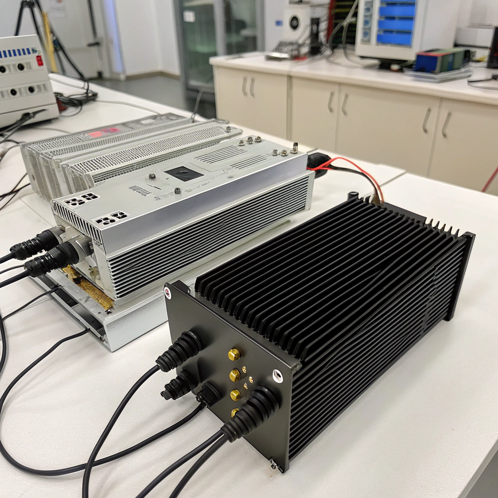
Here I’ll walk through a step‑by‑step approach I use to design a heat sink for multiple power components.
Step 1: Gather device data
You need to collect:
- Power dissipation of each component
- Maximum case/junction temperatures
- Electrical tab configuration
- Mechanical footprint
Step 2: Estimate combined power and required resistance
Use this formula:
[
Rθ{sa} = \frac{T{max} – T{ambient}}{P{total}}
]
Step 3: Select sink geometry
- Use high thermal conductivity materials
- Choose appropriate fin density and size
- Ensure good airflow
- Apply surface treatments to improve heat emission
Step 4: Plan layout
- Place devices close to each other
- Avoid long distance between them
- Ensure flat mounting surface
- Use TIM properly
- Prevent mechanical stress
Step 5: Apply electrical isolation
- If devices are at different voltages, use mica or ceramic pads
- Check that isolation doesn’t add too much thermal resistance
Step 6: Run tests
- Use simulation tools if available
- Prototype and measure case temperatures
- Add margin for dust, ageing, airflow changes
Example table:
| Component | Power (W) | Voltage | Needs Isolation? |
|---|---|---|---|
| MOSFET | 15 | 48V | Yes |
| Diode | 10 | GND | No |
| Regulator | 20 | 24V | Yes |
Devices at different electrical potentials must be isolated when mounted to the same heat sink.True
Mounting tabs at different voltages require insulation to prevent short circuits.
Thermal interface materials increase thermal conductivity between device and heat sink.False
TIMs reduce thermal resistance but do not increase conductivity themselves.
What trends exist in modular cooling solutions?
Cooling demands are growing as power densities increase, so modular cooling systems are becoming more common.
Trends include modular heat sink blocks that attach to multiple devices, re‑configurable fin modules, liquid‑cooled pluggable blocks and standardised interfaces for “cooling cartridges” across different board variants.
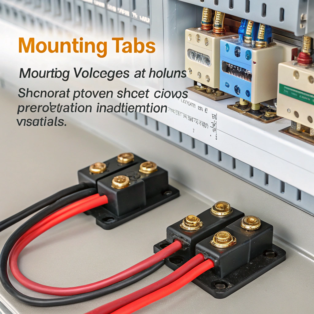
Here are some of the major trends in modular cooling:
Modular base plates
Standard extruded blocks with defined mounting holes allow reuse across different devices.
Configurable fin modules
Clip‑on fins allow scalable cooling. Some systems add fans for higher heat loads.
Liquid cooling
Cold plates and heat pipes are becoming more popular in dense systems.
Plug-and-play thermal cartridges
Standard modules support upgrades and simplify service and replacement.
Digital design
Simulation models of cooling modules are built into design tools, speeding up system-level testing.
Sustainability
Modules reduce waste and allow reuse across product generations.
Modular cooling solutions enable fast adaptation to new power component layouts.True
Standard interfaces and swappable blocks support flexible design.
Modular heat sinks are less efficient than custom ones in every case.False
Properly chosen modular sinks can meet or exceed custom designs depending on the application.
Conclusion
In summary, a single heat sink can safely cool multiple components if you handle layout, power, isolation and geometry properly. Shared sinks offer real cost and performance benefits. Modular cooling trends make it easier to scale and service complex systems.


