
What happens when a heat sink is installed with uneven mounting pressure?
Leading paragraph:
I’ve seen cases where a heat sink looks properly mounted but the device still overheats—because the mounting pressure was uneven.
Featured paragraph:
Uneven mounting pressure causes the heat sink to make poor contact in some areas, leading to increased thermal resistance and reduced cooling performance.
Transition paragraph:
In this article I’ll explain what mounting pressure means, why uneven pressure is a problem, how to make sure force is uniform, and what newer techniques help secure heat sinks better.
What is mounting pressure in heat sink installation?
Leading paragraph:
Picture two surfaces pressed together: if one side isn’t pressed hard enough you’ll get gaps—this is exactly what mounting pressure is about.
Featured paragraph:
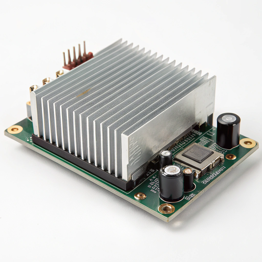
Mounting pressure is the force applied by the heat sink (and its fasteners or clips) onto the component surface so the heat sink base contacts the component and minimizes air gaps, improving heat transfer.
Dive deeper paragraph:
When I talk about “mounting pressure” in a heat sink scenario I mean the clamping or contact force exerted by the heat sink assembly (via screws, springs, clips) onto the device’s heat‑spreading surface (such as a CPU IHS, power module top, etc.). The goal is that the surfaces join with minimal microscopic voids. Real surfaces always have roughness: peaks and valleys. Without sufficient pressure, contact happens only at some of the peaks. The rest of the gap is filled with air, which is a poor thermal conductor. So mounting pressure and contact surface condition both influence what is often called “contact thermal resistance”.
For example, a technical application note from a major semiconductor manufacturer explains that the thermal resistance between case and heat sink (Rθ_cs) depends on both surface roughness and contact pressure. It emphasizes: “The first way to reduce the contact thermal resistance is to increase the contact pressure, which is the joining force.”
In practical assembly terms this means: when you tighten screws or secure clips, you are setting the mounting pressure. Too little and you have weak contact, too much and you risk deforming the package, warping the base or distorting the mounting surface, which also reduces effective contact. The same document warns that excessive mounting torque may cause the package head to distort or lift away, increasing resistance again.
Thus mounting pressure must be sufficient, but also the surfaces must be flat, parallel and clean. Some user‑forum tests show that simply increasing mounting force without verifying contact uniformity can yield little benefit: one test found that when force was above about 45 lbs (≈20 kg) and contact was broad and even, temperatures improved; but when force was similar but contact uneven (most force at edges), cooling improved little or not at all.
In short: mounting pressure is not simply how tight the bolt is—it is how well the heat sink base is pressed, evenly, against the device surface over the full contact area.
Table: Key terms around mounting pressure
| Term | Meaning | Why it matters |
|---|---|---|
| Contact pressure | The actual pressure across the real contact area (force ÷ actual area) | Higher contact pressure ⇒ more real area touching ⇒ fewer gaps |
| Bond line / interface gap | The microscopic or macroscopic gap/voids between surfaces | Gaps increase thermal resistance by replacing metal‑to‑metal contact |
| Clamping force | The force applied by screws/clips to press the heat sink to the device | Determines the mounting pressure and ultimately contact quality |
| Force distribution | How evenly the force/pressure is distributed across the interface | Uneven distribution can localize load and shrink real contact area |
Having defined mounting pressure, next we look at what happens when pressure is uneven.
What problems arise from uneven contact pressure?
Leading paragraph:
I’ve seen overheated assemblies where one side of the heat sink was loose and the other side tight—and the result was hotspots and poor cooling.
Featured paragraph:
Uneven mounting pressure allows air gaps, reduces contact area on parts of the interface, increases thermal resistance, causes hotspots, raises device temperature and degrades reliability.
Dive deeper paragraph:
Let me unpack the issues step by step, based on my assembly experience and the literature.
Air gaps and reduced real contact area
When one region of the heat sink base is not held firmly against the device surface, the gap may widen there. Air replaces what should be metal‑to‑metal interface or well‑filled interface material. Air has very low thermal conductivity compared to metal or good thermal interface material, so that local region becomes a bottleneck. Over the whole interface, if parts are poorly contacted, the effective contact area drops, so heat must traverse a more resistive path.
Hotspots / non‑uniform temperature distribution
Because the heat source (e.g., die) tends to generate heat equally or in certain patterns, but the sink side contact is uneven, some areas are better cooled than others. The “good side” might conduct heat well while the “poor side” lags. As a result you might see local hotspots that heat up faster and may cause thermal throttling or failure. In forum tests of mounting pressure variations, users found that loosening the mounting reduced performance by several degrees Celsius.
Increased overall junction temperature
With increased interface thermal resistance (especially at the case‑to‑sink interface) the overall system thermal path from junction to ambient is degraded. That means for the same heat load, the junction temperature rises. Elevated temperature reduces performance, may accelerate aging (via Arrhenius behaviour for many failure mechanisms), and may shorten the device life.
Mechanical stress and/or deformation
If one fastener is tighter than another, or if the heat sink is mounted with a skew or twist, then mechanical stress may be introduced: warping of the package, bending of the base, or distorting the mounting bracket. Such deformations can lift parts of the heat sink further, paradoxically reducing contact even though the screw is tight. The application note I referenced warns that excessive torque may cause deforming and lifting, increasing contact thermal resistance again.
Reliability and maintenance issues
Uneven mounting pressure may worsen with time: thermal cycling, vibration or differential expansion may cause loosening or shift, further worsening contact. Poor contact may cause TIM pump‑out (where the interface material is squeezed out or migrates), or adhesive pads may degrade faster. Over time this means cooling performance drifts downward, and you may have to re‑mount or re‑apply interface material.
Cost and performance impact
From my practical view: what might have been a minor mounting variation becomes a major cost down‑the‑line. If you design for a certain thermal budget but depend on good contact, uneven mounting means you lose margin. You might need a larger heatsink, bigger fan or more expensive cooling just to compensate. In production runs, yield may suffer.
In short: uneven mounting pressure is a subtle but real threat to thermal design. Even when you’ve selected a good heatsink and interface material, the mounting step can undermine everything unless done properly.
How can I ensure uniform mounting force?
Leading paragraph:
From my hands‑on experience I know that achieving uniform mounting force is not just about tightening screws—it’s about surfaces, fixtures and verification.
Featured paragraph:
You ensure uniform mounting force by preparing flat surfaces, applying correct interface material, using calibrated fasteners or springs, distributing force evenly (e.g. star‑pattern tightening), checking contact area, and verifying via measurement if needed.
Dive deeper paragraph:
Here’s a guide to how I approach uniform mounting force, step by step, with practical tips.
1. Prepare and inspect mating surfaces
Before mounting I always check that both the heat sink base and the device surface are flat within tolerances, free of contamination (dust, machining burrs, residue). For example, the technical guide states that the mounting surface should have flatness ≤ 16 µm (over specified length) and surface finish ≤ 0.02 mm. Poor surface prep means you start with uneven contact regardless of force.
2. Choose and apply proper thermal interface material (TIM)
Even if mounting pressure is perfect, if you skip TIM or apply it wrong you’ll reduce performance. The TIM fills microscopic voids and complements the mounting pressure. But note: TIM performance still depends on pressure because if the interface is loosely held, the TIM may not spread evenly or may leave voids. So choose a suitable TIM/pad thickness, apply evenly, remove air bubbles, and cover the area consistently.
3. Use appropriate fastener or clip system
Whether you use screws, bolts, clips or springs matters. The joining method must provide consistent preload/force and allow even distribution. For screws: use correct torque, but also ensure all screws share the load evenly by tightening in a defined sequence (e.g., cross/diagonal pattern) to avoid skewing. For clips or springs: use calibrated springs or clips designed to apply consistent force and hold it under thermal cycling.
4. Use spacers, shims, washers if needed
If the mounting holes or surfaces are slightly mis‑aligned, or if one side is higher than the other, you may need washers or shims to equalise the height and ensure all fasteners share the load. For example, users have added extra washers under GPU cooler mounts to increase pressure and make the load more even around the surface.
5. Tightening sequence and torque specification
I always follow or define a tightening sequence: start by loosely tightening all fasteners to bring the sink into contact, then tighten in a pattern so force builds evenly. Avoid fully tightening one side first then the other, which causes one side to load first and the other to lag. Use a calibrated torque wrench or measurement when possible.
6. Verification of contact and force distribution
In higher‑reliability or production settings you may insert pressure‑sensitive film or sensors between the heat sink and device to map contact pressure. This helps catch uneven contact that might not be visible. Some test results showed that when average force was adequate but distribution was skewed, thermal performance suffered.
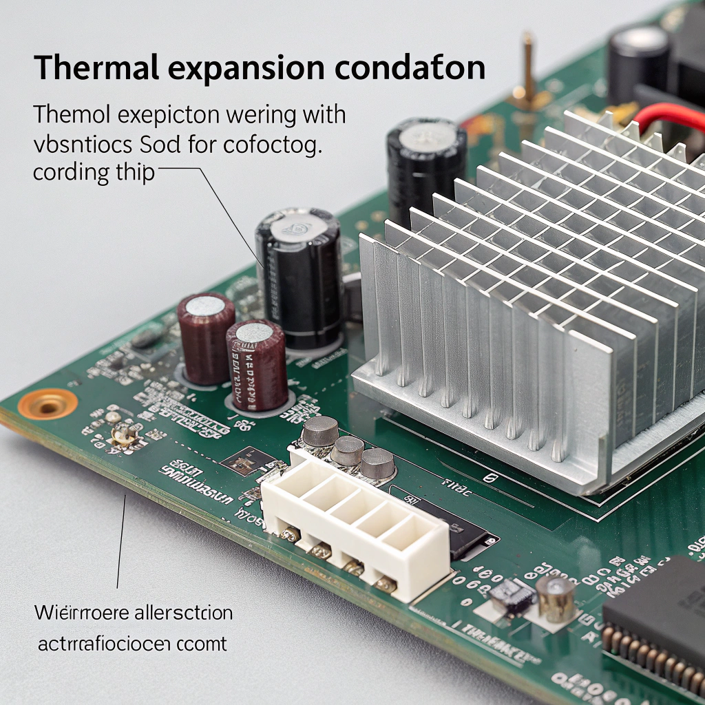
7. Consider environmental effects (thermal cycling, vibration)
Even if you mount well initially, thermal expansion/contraction and vibration may loosen or shift the heat sink, thereby degrading contact pressure over time. Use locking washers, spring‑clips, retainers or adhesives (where appropriate) to maintain preload. Also schedule periodic inspection in critical systems.
8. Document the process for consistency
If you are in manufacturing or deploy many units, document the mounting process: specify torque values, sequence, surface prep checklist, TIM type/thickness, and inspection step. This ensures reproducible results rather than “it worked once” and hope for the same again.
Table: Checklist for ensuring uniform mounting force
| Step | Action | Why it matters |
|---|---|---|
| Surface prep | Flatten, clean, remove burrs & contaminants | Ensures real contact area is maximised |
| TIM selection & application | Choose correct type, apply uniformly | Enhances contact and fills micro‑voids |
| Fastener/clip method | Use correct hardware, calibrated torque or preload | Provides consistent clamping force |
| Force distribution | Use tightening sequence, spacers/shims if needed | Spreads force evenly, avoids skew |
| Verification | Use pressure film or sensors where feasible | Confirms actual contact pressure and distribution |
| Environmental retention | Use springs, locking washers, check after cycling/vibration | Maintains contact over life of system |
By following these steps I’ve reduced mounting‑related cooling failures and improved repeatability. Ensuring uniform mounting force makes the difference between a good cooling design and a compromised one.
What are the new techniques for secure heat sink attachment?
Leading paragraph:
In recent years I’ve watched mounting techniques evolve further—moving beyond just screws and clips into measurement, specifically designed hardware and bonded interfaces.
Featured paragraph:
Modern secure heat sink attachment techniques include pressure‑mapping verification, pre‑loaded spring/clip systems, bonded copper patch technologies (which reduce reliance on clamping pressure), and modular mounting hardware for consistent force and repeatability.

Dive deeper paragraph:
In my experience staying current with these newer mounting methods helps when you design high‑performance or high‑reliability systems. Here are several techniques, with pros and cons.
Pressure‑mapping and real‑time contact measurement
In advanced assembly, engineers use thin pressure‑sensitive films or sensors between heat sink and component surface to measure actual contact pressure distribution. The data show load hotspots, voids, or skewed mounting. With that knowledge you can adjust fixture geometry, clip placement or shim thickness before full assembly. This turns mounting from guess‑work to measured practice.
Pre‑loaded spring/clip systems
Instead of just relying on screws, many high‑end designs use spring‑loaded clips, constant‑force springs or preload mechanisms. These apply a defined force and maintain it even when the device expands/contracts under thermal cycling. The advantage is better retention of mounting pressure and more even distribution. For example, clip mounting is cited as being more stable and providing more uniform pressure distribution compared to screw mounting in some semiconductor application notes.
Bonded copper patch / soldered attachment (e.g., “PowerSite” technology)
One newer method replaces mechanical clamping with a direct soldered attach of the device to a copper patch on the heat sink. A major semiconductor manufacturer technical note describes “PowerSite” which removes screws/clips altogether and thus the dependence on mounting pressure. Because the soldered joint ensures close contact, the mechanical variability is reduced. This is excellent for modules where serviceability is less critical. The con is that it complicates rework and may increase cost or assembly complexity.
Modular mounting hardware with force control
In industrial or high‑volume production, mounting hardware is evolving: torque‑controlled screws, load‑cells integrated in fixtures, Belleville washers to limit deformation, and mounting frames that guarantee parallel alignment of surfaces. These help ensure each unit is mounted within a narrow force distribution band, reducing variation.
Improved surface engineering and base‑plate geometry
Another trend is designing the heat sink base and mounting interface to better match the package: e.g. heat sink bases with controlled curvature to match typical die bow of CPUs, or pre‑machined base surfaces with defined flatness, and using spacers to match the assembly height. This way the mounting pressure becomes less dependent on brute force and more on engineered fit.
Interface materials tuned for mounting pressure
Although strictly not a mounting hardware technique, newer TIMs and interface pads are optimized for specific pressure ranges and thicknesses so that the combination of mounting force + interface material yields predictable thermal performance. When the mounting force is defined by clips or hardware, you can choose an interface material that compresses to the correct thickness and maintains good thermal conduction, reducing variability in field assembly.
Summary of emerging techniques with pros & cons:
| Technique | Benefits | Considerations |
|---|---|---|
| Pressure‑mapping verification | Quantifies contact pressure and distribution | Requires extra equipment and time in assembly |
| Pre‑loaded spring/clip systems | Better preload retention under thermal cycling | Must match geometry and may cost more than screws |
| Bonded copper patch / solder attachment | Removes variability of fasteners | Harder to service, higher assembly complexity |
| Modular mounting hardware with control | Ensures repeatable force across units | Higher cost, may need fixture redesign |
| Tailored base geometry / interface fit | Reduces need for extreme force, better fit | Requires design matching to specific package type |
| TIM/interface materials tuned to force | Reduces variability from mounting force variation | Needs manufacturing and material cost discipline |
From my view: if you’re designing for standard consumer systems you may still rely on screw mounting with good process. But if you are in power modules, industrial electronics, or large heat sinks where thermal margin is tight, these newer techniques become very helpful.
Conclusion
In summary, uneven mounting pressure when installing a heat sink is a hidden but significant risk. It can reduce contact area, increase thermal resistance, cause hotspots, raise device temperature and shorten lifespan. By understanding what mounting pressure is, recognising the problems of uneven contact, applying best practices to ensure uniform force and adopting newer secure attachment techniques, you can greatly improve thermal performance and reliability. A well‑mounted heat sink isn’t just “tight enough”—it’s engineered, measured and repeatable.


