
Aluminum extrusion machining precision levels?

Many builders and engineers face the headache of shapes that don’t fit just right. Poor extrusion precision can lead to parts that won’t align. Without proper finish, projects stall or fail.
Understanding real tolerance levels after extrusion helps avoid wasted time and materials.
Transitioning from raw extrusion to ready-to-use aluminum parts matters a lot for fit and function. If you rely only on extrusion, you may run into mismatch problems. This article walks through what precision you can expect after extrusion, how machining helps, and how to check your parts.
What precision levels are achievable after extrusion?
Raw extrusion often brings surprises. Dimensions may stray from the ideal by quite a bit. In a few cases the deviation is small. But often parts are not precise enough for tight assemblies.
Typical tolerance from standard aluminum extrusion lies near ±0.5 mm to ±1.5 mm on many dimensions.

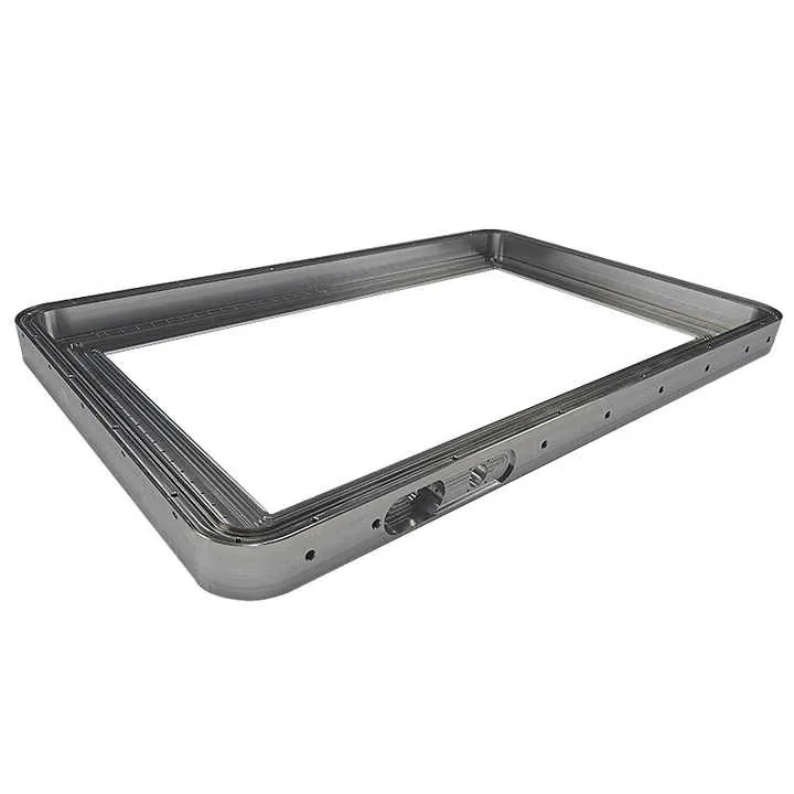
After an extrusion run, the final cross section can deviate because of die wear, cooling shrinkage, and pulling irregularities. These factors mean that nominal sizes on paper may differ. Length along the extrusion may stay close, but details like slot width, wall thickness, or groove alignment can shift. For example, a slot meant to be 10.00 mm wide may come out as 9.4 mm or 10.6 mm depending on process control. Also, walls may be slightly uneven. If a part is meant for housing electronics or aligning parts, these variances can cause misfit.
When tolerances like ±0.5 mm matter, raw extrusion alone often fails. Larger frame work like window frames or fencing does not rely on precision, so small variance is fine. But machines, enclosures, or assemblies requiring tight fit suffer.
Part of the issue is that extrusion elongates and cools. Cooling causes shrinkage. The tool or mold — the die — wears down over time, shifting shape. Pulling speed and temperature influence final dimensions. Because of these changing factors, extrusion output has natural variation. And because the process aims at speed and throughput, tight control is hard.
Thus, extrusion-only parts are good for structural frames or rough assemblies. But for precision assemblies or mechanical parts, expecting tight fits from extrusion alone is risky.
| Use case | Acceptable tolerance | Comments |
|---|---|---|
| Structural frame | ±1.0 mm to ±1.5 mm | Fine for general construction |
| Architectural profiles | ±0.5 mm to ±1.0 mm | Walls or trim where small variance ok |
| Mechanical parts | Not recommended | Variance may break fit or alignment |
In short, extrusion-only parts often do not meet precision needs for tight mechanical or assembly works.
How does post‑machining improve extrusion accuracy?
Leaving raw extrusion as-is often leads to poor fit. That hurts assembly speed and final product quality. Post‑machining fixes many of these problems. It smooths surfaces, corrects size, and ensures accurate holes or grooves.
With good machining, tolerance can improve to about ±0.05 mm to ±0.15 mm, suitable for tight mechanical fit or precise assembly.
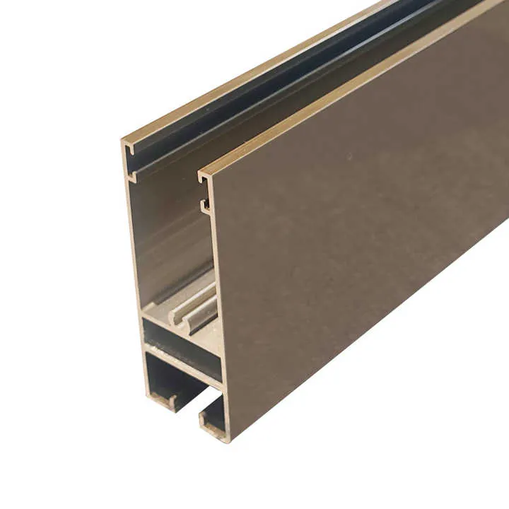
Machining after extrusion means using tools like CNC milling or drilling to cut, shape, or finish parts precisely. The process often begins with removing irregular edges or excess material — a kind of “cleanup.” Then final shapes, slots, holes, or surfaces are cut to exact dimensions. CNC machines follow digital designs precisely. The machines handle variations in the raw metal. They adjust cuts to meet design needs, rather than relying on extrusion alone.
Because machining can correct slot widths, straighten uneven walls, and ensure flat surfaces, machined parts are much more reliable. A groove that was too narrow becomes perfect. A wall that was slightly angled becomes true. Flat faces become flat and parallel. Even length can be cut precisely. When you need exact hole placement, proper alignment, smooth finishes or tight mates, machining after extrusion makes these possible.
Here is a general guideline of tolerance improvement:
| Stage | Typical Tolerance | Typical Use Case |
|---|---|---|
| Raw extrusion | ±0.5 mm – ±1.5 mm | Frame or non‑critical parts |
| Post‑machining | ±0.05 mm – ±0.15 mm | Precision assemblies |
Because machining machines follow a precise CAD model, the final output matches design closely. This lowers chance of part mismatch or assembly errors.
Also, machining often improves surface finish. Extruded aluminum may have rough surfaces or slight ridges. Machining cuts and polishes surfaces. This helps when parts must slide, fit tightly, or receive coatings. Machined parts often look cleaner too.
Using post‑machining is not just about fixing size. It ensures reliability, reduces waste, and saves effort later. I find that for parts needing strong quality, machining is not optional.
Are tight tolerances feasible without CNC finishing?
It is tempting to skip machining to save time and cost. But sometimes that choice causes big problems. Without machining, achieving tight tolerances is hard. Variations from die wear and cooling make repeatability poor.
Tight tolerances for critical parts are rarely feasible without CNC or proper finishing.

If a project requires holes aligned within ±0.1 mm, or slot width to fit a board closely, relying only on extrusion will likely fail. The inherent variation in raw extrusion makes output inconsistent. Even small shifts in temperature or pulling speed can change final dimensions noticeably. Without a process that corrects those changes, you risk part mis‑fit, bulky gaps, or stress in the assembly.
One could try to force tighter control of the extrusion process. But that adds cost, slows production, and still gives no guarantee. Die wear alone can cause drift. Even if the first batch is okay, the next may diverge.
Moreover, some shapes just cannot hold tolerance in extrusion alone. Thin walls, tight slots, precise holes require material removal or shaping. Extrusion cannot drill or cut; it just pushes material through a shape. That means internal holes or complex contours do not come out precise.
Therefore skipping machining is usually safe only for crude, non‑precise parts. For any part needing fit, alignment, or further processing, CNC or similar finishing is essentially required.
In rare cases, if the part is large and tolerance requirement is loose (for example, a simple aluminum rail), extrusion alone might work. But that is not the norm for quality manufacturing or parts for machinery.
What tools are used to verify machining precision?
Producing parts is only half the work. Ensuring they meet tolerance needs proper measurement. Without accurate check, errors slip through. Good measuring tools help catch those errors early.
Common tools include calipers, micrometers, height gauges, coordinate measuring machines (CMMs), and optical comparators.
Below are typical tools used in verifying aluminum parts after machining:
Measuring tools overview
| Tool Type | Typical Resolution | Best For |
|---|---|---|
| Vernier / digital caliper | 0.01 mm (±0.02 mm) | Length, slot width, outer dims |
| Micrometer | 0.001 mm (±0.005 mm) | Wall thickness, shaft diameters |
| Height gauge + surface plate | 0.02 mm+ depending on user | Flatness, step heights |
| Coordinate Measurement Machine (CMM) | 0.005 mm or better | Complex geometry, hole patterns |
| Optical comparator / profile projector | depends on magnification — ~0.01 mm | Profile accuracy, slot/groove shape |
Use of calipers and micrometers
Simple tools like calipers and micrometers give quick checks. For example, you can check slot width, wall thickness, or external dimension easily. These tools are inexpensive and widely available. They help check many parts rapidly. For rough checks or standard tolerance levels, these tools work well.
Flatness and height accuracy
Using a surface plate with a height gauge helps test if surfaces are flat or parallel. When machined parts must mate with other parts, flatness matters. Height gauges can measure how even two surfaces are. This helps catch warping or uneven cut.
Complex geometry — CMM and optical tools
For parts with many features, holes, angled cuts, or tight pattern spacing, a higher level of measurement is necessary. A coordinate measuring machine (CMM) uses probes or lasers to scan many points on the part. The machine compares actual measurements against the CAD model. It reports deviations in all directions. This method is very accurate and repeats reliably for many parts.
Optical comparators (profile projectors) help when you need to check shape profiles, slot geometry, or edge definition. They project a magnified silhouette of the part onto screen. Then you compare against overlay or drawing. They help show small imperfections or mis‑shapes that may cause issues.
Regular measurement ensures each batch meets quality. Without measurement, bad parts may pass, leading to rework or assembly problems.
Conclusion
Choosing aluminum extrusion alone saves cost and time but limits precision. Post‑machining elevates quality and allows tight tolerances for real‑world assemblies. Reliable machining plus proper measurement ensures fit, finish, and consistency.


