
Aluminum extrusion custom profile design rules?

Many buyers struggle with aluminum extrusion design. Bad rules lead to high cost, long lead time, and weak parts. This article breaks the rules down in a simple way.
Aluminum extrusion custom profile design follows clear rules about wall thickness, shape balance, cavity limits, and material flow. When these rules are respected, profiles are easier to produce, cheaper, and more stable in quality.
These rules come from real factory practice, not theory. Understanding them helps buyers avoid redesigns, scrap, and delays.
What guidelines apply to custom extrusion design?

Poor design choices often look fine on drawings but fail on the press. This creates delays and hidden cost.
Good custom extrusion design follows guidelines that support smooth metal flow, balanced shape, simple tooling, and stable tolerances. These guidelines reduce risk and improve consistency across production batches.
The rules below come from daily production experience and tooling limits.
Start from function, not shape
Every profile must start with use, not appearance. The first step is to define what the profile must do.
Questions that must be clear:
- Does it carry load or only cover?
- Does it need tight tolerance or loose fit?
- Is it structural or decorative?
When function is clear, design becomes simpler. Overdesign is one of the most common mistakes.
Keep geometry balanced
Balanced profiles extrude better. When mass is evenly distributed, aluminum flows at similar speed through the die.
Unbalanced shapes cause:
- Twisting
- Bending
- Uneven wall thickness
- Surface defects
A good rule is symmetry around the center line when possible.
Avoid sharp corners
Sharp internal corners block metal flow. This raises pressure and shortens die life.
Recommended practice:
- Internal corner radius >= 0.5 x wall thickness
- External corners slightly rounded
This improves surface quality and reduces cracking.
Match tolerance to real need
Tight tolerance increases cost. Many buyers request tight numbers without real need.
Common results:
- Lower yield
- More scrap
- Slower speed
Only critical dimensions should be tight.
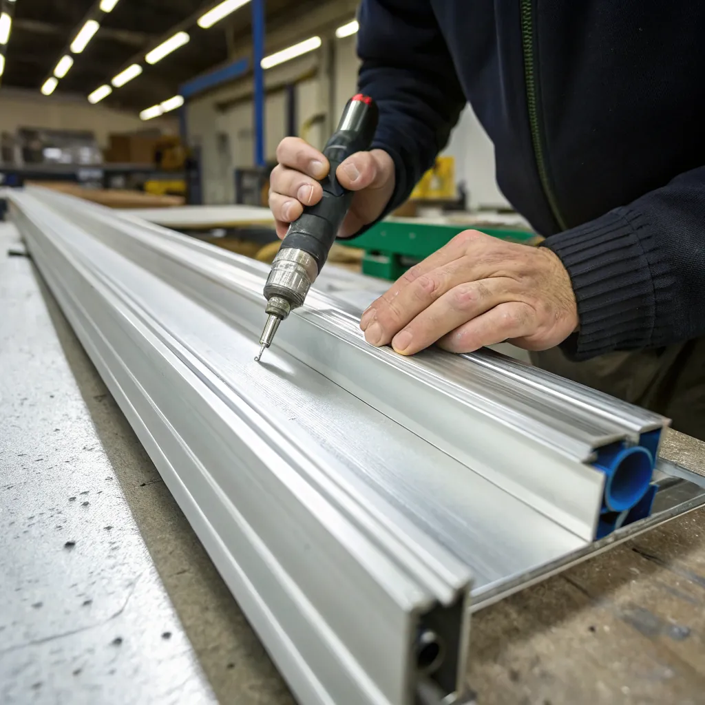
Design with tooling in mind
Every profile must be cut from a steel die. If a shape cannot be machined or assembled in a die, it cannot be extruded.
Designers must respect:
- Die steel strength
- Bearing length limits
- Bridge and port layout
Below is a simple table showing good vs risky design choices.
| Design aspect | Good practice | Risky practice |
|---|---|---|
| Shape balance | Symmetrical | Heavy on one side |
| Corners | Rounded | Sharp 90 degree |
| Features | Simple slots | Thin deep grooves |
| Tolerance | Function based | Over tight |
These guidelines are not optional. They decide if a design runs smoothly or fails during trial.
Balanced geometry improves metal flow and extrusion stability.True
Even mass distribution allows aluminum to flow evenly through the die, reducing twisting and defects.
Sharp internal corners make extrusion easier and cheaper.False
Sharp corners restrict metal flow and increase pressure, which raises cost and tooling risk.
How does wall thickness affect design feasibility?

Wall thickness is one of the first checks in extrusion review. Many designs fail here.
Wall thickness directly affects extrusion speed, die strength, surface quality, and cost. Too thin walls risk breakage, while too thick walls waste material and slow production.
Finding the right range is critical.
Minimum wall thickness limits
Each alloy and press size has a minimum wall limit. For most common alloys like 6063, thin walls are possible but not unlimited.
Typical practical ranges:
- Small profiles: 0.8 mm to 1.2 mm
- Medium profiles: 1.2 mm to 2.0 mm
- Large profiles: 2.0 mm and above
Below these values, problems appear.
Problems caused by thin walls
Thin walls create many issues:
- Metal cools too fast
- Flow becomes unstable
- Breakage at die exit
- High scrap rate
Thin sections also distort more during quenching and stretching.
Problems caused by thick walls
Very thick walls are not always better.
They cause:
- Slow extrusion speed
- Higher energy use
- Longer cooling time
- More material cost
Thick sections may also cool unevenly, leading to internal stress.
Keep wall thickness uniform
Uniform wall thickness is more important than absolute thickness.
Large differences cause:
- Uneven flow
- Warping
- Surface lines
If variation is required, transitions should be smooth.
Thickness ratio rule
A common rule used in factories:
- Max wall thickness should not exceed 3x the minimum wall thickness
This keeps flow balanced and reduces distortion.
Below is a simple comparison table.
| Wall thickness choice | Result |
|---|---|
| Uniform thickness | Stable extrusion |
| Very thin walls | Breakage risk |
| Very thick walls | Slow speed |
| Large variation | Warping |
Wall thickness also affects finishing. Thin walls dent easily during handling. Thick walls increase anodizing cost.
Designers should choose thickness based on:
- Strength need
- Profile size
- Alloy choice
- Surface finish requirement
Uniform wall thickness improves extrusion quality and reduces distortion.True
Even thickness allows consistent metal flow and cooling across the profile.
Thicker walls always improve strength without drawbacks.False
Excessive thickness increases cost, slows extrusion, and can cause cooling stress.
Are there limits on internal cavities and hollows?
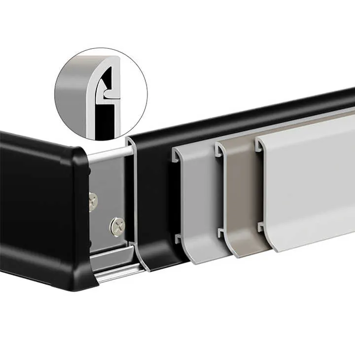
Hollow profiles are popular but not unlimited. Internal cavities add complexity.
Internal cavities and hollows are limited by die strength, metal flow, and press capacity. More cavities increase tooling cost and production risk.
Understanding these limits prevents redesign later.
Solid vs hollow vs semi hollow
Profiles fall into three types:
- Solid: no enclosed void
- Semi hollow: partially enclosed
- Hollow: fully enclosed cavities
Each type needs different tooling.
Hollow die structure basics
Hollow profiles require:
- Bridges
- Ports
- Mandrels
- Welding chamber
Aluminum splits, flows around bridges, and rewelds. This process has limits.
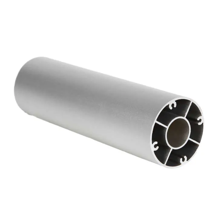
Limits on cavity size
Large cavities weaken die steel.
General practice:
- Cavity width should not exceed die steel support limits
- Thin walls around cavities need extra thickness
If cavities are too large, die may crack.
Limits on number of cavities
More cavities mean:
- More bridges
- More welding lines
- Higher pressure
This increases:
- Tooling cost
- Scrap risk
- Lead time
Most profiles work best with one or two main cavities.
Weld line considerations
Where metal rejoins, weld lines form. These affect:
- Strength
- Surface appearance
- Anodizing quality
Critical load areas should avoid weld lines.
Aspect ratio of hollows
Long narrow cavities are risky. Metal may not fill evenly.
Design tips:
- Avoid very deep narrow hollows
- Increase wall thickness around them
- Add ribs for support
Below is a comparison table.
| Hollow feature | Low risk | High risk |
|---|---|---|
| Cavity count | 1-2 | 4+ |
| Cavity width | Moderate | Very wide |
| Wall around hollow | Thick | Very thin |
| Shape | Simple | Complex |
Hollow design must always consider press size. What works on a 4500 ton press may fail on a smaller one.
Hollow profiles require bridges and welding chambers in the die.True
Hollow extrusion depends on metal splitting and rewelding around die bridges.
There is no practical limit on the number of internal cavities.False
More cavities increase pressure and weaken die structure, raising failure risk.
Can design choices reduce production waste?
Waste is often designed in at the drawing stage. Small changes save large cost.
Smart extrusion design reduces production waste by improving yield, reducing scrap, increasing speed, and extending die life. These savings repeat on every batch.
Waste reduction is not only about material.
Reduce unnecessary mass
Extra thickness adds weight without function.
Results:
- Higher billet use
- More machining chips
- Higher freight cost
Design should match strength needs, not guesses.
Simplify profile features
Complex features slow extrusion.
Examples:
- Deep narrow slots
- Tiny ribs
- Decorative shapes with no function
Simpler profiles:
- Run faster
- Have fewer defects
- Lower die cost
Improve nesting and cutting length
Design length and shape affect cutting loss.
Consider:
- Standard billet length
- Press run length
- Saw kerf loss
Small adjustments in length can reduce end scrap.
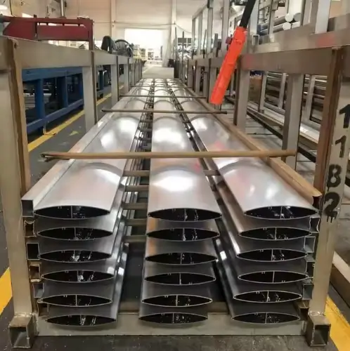
Design for downstream processes
Extrusion does not end at press exit.
Consider:
- Anodizing racks
- CNC clamping
- Packing method
Profiles that are easy to handle get less damage.
Extend die life through design
Die replacement creates waste:
- Tool steel
- Trial scrap
- Setup time
Design choices that extend die life:
- Avoid thin die tongues
- Avoid extreme bearing differences
- Avoid sharp corners
Below is a simple waste reduction table.
| Design choice | Waste impact |
|---|---|
| Simplified shape | Less scrap |
| Balanced thickness | Higher yield |
| Standard length | Less cutoff loss |
| Strong die design | Longer tool life |
Waste reduction also improves delivery time. Faster runs mean more stable schedules.
Design teams that understand extrusion reduce cost without touching price negotiation.
Simpler extrusion designs generally reduce scrap and increase speed.True
Simple shapes improve metal flow and reduce defect risk, leading to higher yield.
Production waste is mainly controlled after extrusion, not during design.False
Most waste is determined by profile design before production begins.
Conclusion
Good aluminum extrusion design follows clear rules. Balanced shapes, proper wall thickness, realistic hollows, and simple features reduce risk. When design supports the process, cost drops and quality becomes stable. This is where real value starts.

