
Wie dick sollte ein Kühlkörper sein, um die Wärme effizient abzuleiten?
Ein großer, sperriger Kühlkörper bedeutet nicht immer eine bessere Kühlung - ich habe schon kompakte Designs gesehen, die besser funktioniert haben, nur weil die Dicke und die Geometrie richtig waren.
Die richtige Dicke eines Kühlkörpers hängt von der Rolle des Sockels und der Lamellen ab: Der Sockel verteilt die Wärme von der Quelle, und die Lamellen geben sie an die Luft ab. Beide müssen ausgewogen sein, nicht maximal groß.
Sehen wir uns an, was die ideale Dicke bestimmt, warum die Lamellengeometrie wichtig ist, wie man effizient konstruiert und welche modernen Trends die Materialien von Kühlkörpern prägen.
Was bestimmt die optimale Dicke des Kühlkörpers?
Manche Kühlkörper versagen, selbst wenn sie riesig sind - in der Regel, weil ihre Basis zu dünn ist oder die Rippen zu dicht beieinander liegen. Ich habe das schon ein paar Mal erlebt, als ich Kunden bei der Neugestaltung geholfen habe.
Die beste Dicke ist ein Gleichgewicht zwischen Wärmeleitfähigkeit, Lamelleneffizienz, Ausbreitungswiderstand der Basis, Luftstrom und Größenbeschränkungen. Man kann nicht einfach alles dick machen und erwarten, dass es funktioniert.
Ich habe es folgendermaßen herausgefunden:
Was zu beachten ist
| Faktor | Auswirkung auf die Dicke |
|---|---|
| Dicke der Basis | Hilft bei der Verteilung der Wärme über die Flossenfläche |
| Dicke der Lamellen | Beeinflusst, wie gut die einzelnen Rippen Wärme leiten |
| Abstand zwischen den Lamellen | Kontrolliert Luftstrom und Oberfläche |
| Art des Materials | Kupfer braucht weniger Dicke als Aluminium |
| Luftstrom | Natürliche oder erzwungene Konvektion ändert das Design |
| Anwendungsgrenzen | Größe, Gewicht und Kosten spielen eine Rolle |
Ein zu dünner Boden kann die Wärme nicht gut verteilen. Zu dünne Flossen leiten möglicherweise nicht genug Wärme ab. Aber alles dicker zu machen, erhöht das Gewicht und die Kosten und kann den Luftstrom verringern.
Typische Werte
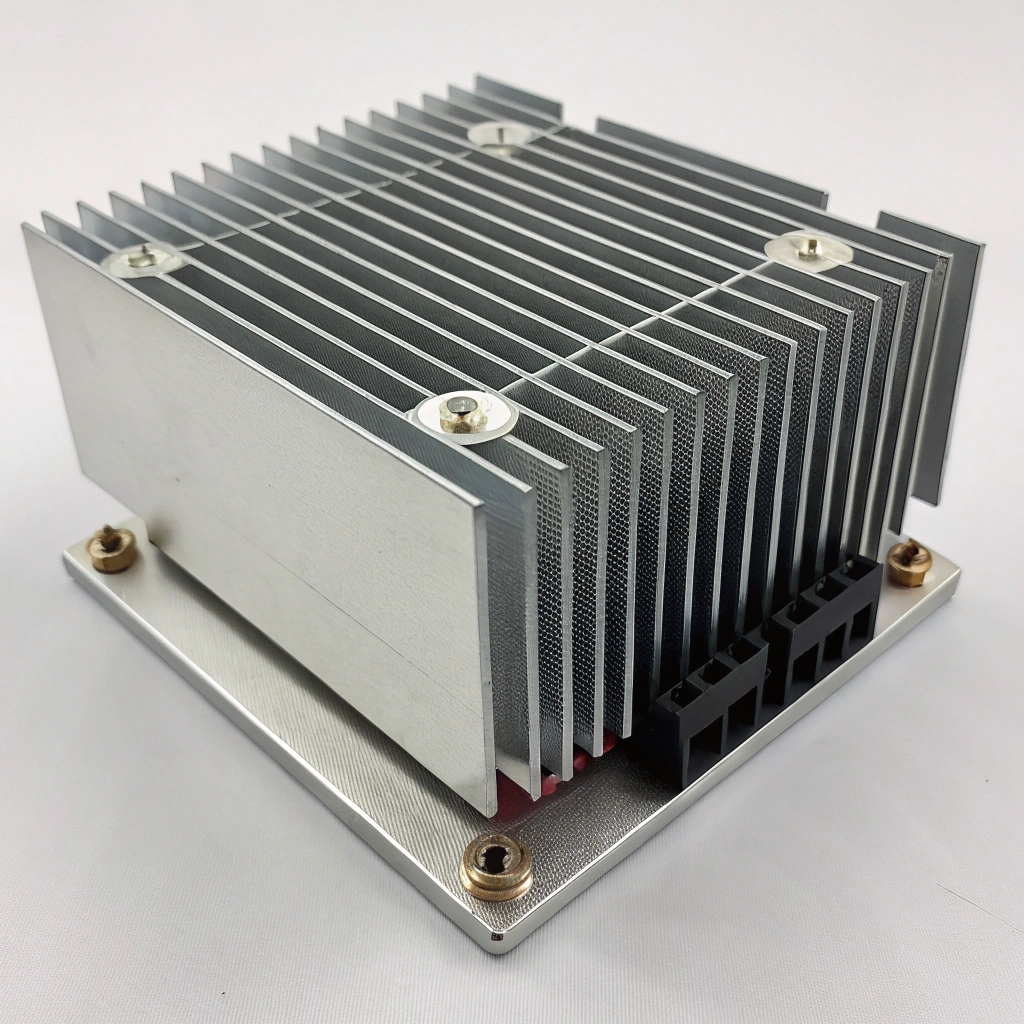
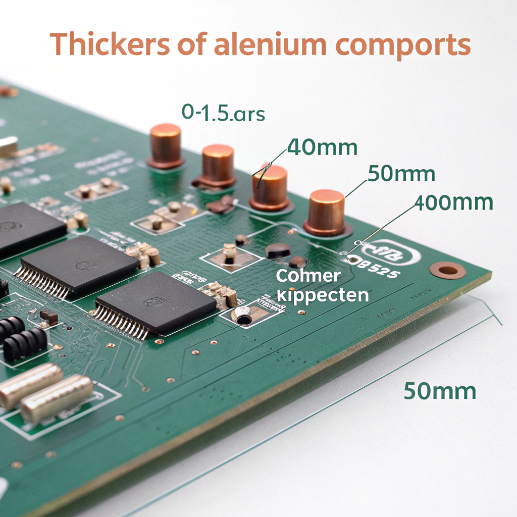
- Dicke der Basis: Oft 5-10 mm bei stranggepresstem Aluminium; mehr bei Kupfer.
- Dicke der Lamellen: Etwa 0,5-1,5 mm für Aluminium; 0,2-0,6 mm für Kupfer.
- Abstände: In der Regel >4 mm bei Ausführungen mit natürlicher Konvektion.
- Höhe der Flosse: Hängt vom Luftstrom und der Bauart ab, in der Regel jedoch 20-50 mm.
Ziel ist es, dass die Wärme von der Quelle in den Sockel fließt, sich gleichmäßig verteilt, dann in die Lamellen gelangt und an die Luft abgegeben wird. Wenn ein Teil dieser Kette einen hohen Widerstand aufweist, leidet die Leistung.
Dickere Grundplatten ergeben immer eine bessere Kühlkörperleistung.Falsch
Nur bis zu einem gewissen Punkt. Ab einer bestimmten Dicke hilft mehr Metall nicht mehr, weil die Luftkühlung zum Engpass wird.
Die Lamellendicke beeinflusst die Leitfähigkeit und den Luftstrom - beides muss für eine gute Leistung ausgeglichen sein.Wahr
Zu dünne Lamellen können die Wärme nicht gut ableiten, und zu dicke Lamellen blockieren den Luftstrom.
Was sind die Vorteile der richtigen Flossengeometrie?
Ich habe einmal gesehen, wie ein Design bei thermischen Tests durchgefallen ist - nicht, weil das Material falsch war, sondern weil die Rippen zu dicht beieinander lagen und den Luftstrom blockierten. Eine Änderung des Rippenabstands brachte Abhilfe.
Eine gut durchdachte Rippengeometrie verbessert die Kühlung, indem sie die Oberfläche vergrößert, einen gleichmäßigen Luftstrom ermöglicht und jede einzelne Rippe effektiv macht.
Warum Geometrie wichtig ist
- Oberfläche: Mehr Fläche = bessere Wärmeübertragung, solange sich die Luft bewegen kann.
- Luftstrom: Die Luft braucht Platz zwischen den Lamellen. Zu eng bedeutet schlechte Kühlung.
- Wirkungsgrad der Lamellen: Lange, dünne Flossen bleiben in der Nähe der Spitzen möglicherweise nicht heiß genug.
- Verwendung des Materials: Eine gute Geometrie verbraucht weniger Metall für dieselbe Leistung.
- Orientierung: Vertikale Lamellen unterstützen die natürliche Konvektion; quer geschnittene Lamellen eignen sich für Zwangsluft.
Tipps, die funktionieren
| Geometrie-Regel | Nutzen Sie |
|---|---|
| Lamellenabstand ≥ 4 mm | Verhindert die Blockierung des Luftstroms |
| Flossenhöhe < 45×Dicke | Hält die Herstellung und die Kosten realistisch |
| Stiftlamellen für Zwangsluft | Verarbeitet multidirektionalen Fluss |
| Aufgeweitete Lamellen für natürliche Konvektion | Verbessert den vertikalen Luftstrom |
Ich verwende sie, wenn ich Kunden berate. Es geht nicht darum, zu raten, sondern zu testen, welche Form Wärme und Luft zusammenfließen lässt. Das ist es, was zu echten Ergebnissen führt.
Die Rippengeometrie dient lediglich der mechanischen Unterstützung und hat keinen Einfluss auf die Kühlkörperleistung.Falsch
Lamellenabstand, -form und -dicke wirken sich direkt auf Luftstrom, -leitung und -konvektion aus.
Zu dicht beieinander liegende Lamellen können die Wärme stauen und die Leistung verringern.Wahr
Enge Abstände schränken den Luftstrom ein und führen zu Hotspots und schlechter Konvektion.
Wie kann ich einen Kühlkörper mit idealer Dicke entwerfen?
Ich beginne immer mit dem Problem, das wir lösen wollen: wie viel Wärme, wie schnell und wohin sie geht. Von dort aus arbeite ich mich zurück zu den Abmessungen und Materialien.
Bei der Entwicklung der idealen Dicke müssen Sie die Leistungsaufnahme, die Materialgrenzen, den Luftstrom und die Größenbeschränkungen kennen. Es ist ein schrittweises Gleichgewicht, kein Ratespiel.
Schritt-für-Schritt-Plan
-
Thermisches Ziel definieren
- Leistungsaufnahme (W)
- Maximal zulässiger Temperaturanstieg (°C)
- Soll-Wärmewiderstand (°C/W)
-
Material auswählen
- Aluminium für leichte, kostengünstige Systeme
- Kupfer für kompakte, leistungsstarke Spülen
-
Bodenstärke wählen
- Dünn, wenn die Wärmequelle breit ist
- Dick, wenn die Wärmequelle klein und zentral ist
-
Lamellenprofil auswählen
- Dicke: 0,5-1,5 mm (Al), 0,2-0,6 mm (Cu)
- Höhe: 20-50 mm
- Abstände: ≥4 mm (natürliche Konvektion)
-
Simulieren oder Berechnen
- Verwenden Sie einen Taschenrechner oder eine CFD-Software
- Basiswiderstand + Lamellenleistung prüfen
-
Anpassen und iterieren
- Zu heiß? Dickerer Boden oder mehr Lamellen
- Zu schwer? Dünnerer Boden oder kürzere Flossen
Beispielfall
| Parameter | Wert |
|---|---|
| Wärmebelastung | 50 W |
| Maximaler Temperaturanstieg | 40 °C |
| Zielwiderstand | 0,8 °C/W |
| Material | Aluminium 6063 |
| Dicke der Basis | 8 mm |
| Dicke der Lamellen | 1,2 mm |
| Abstand zwischen den Lamellen | 5 mm |
| Ergebnis | Zielerfüllung mit Marge |
Die Konstruktion von Kühlkörpern beginnt mit den thermischen Zielen, nicht nur mit den Abmessungen.Wahr
Ohne Kenntnis der Wärmebelastung und der Temperaturgrenzen kann man nicht die richtige Dicke auslegen.
Dickere Rippen verbessern immer die Leistung des Kühlkörpers.Falsch
Sie könnten die Anzahl der Lamellen und die Oberfläche verringern, was den Luftstrom und die Kühlung beeinträchtigen kann.
Welche Fortschritte gibt es bei leichten Kühlkörpern?
Heutzutage wollen die Kunden kleinere und leichtere Systeme - vor allem für Elektrofahrzeuge, Drohnen und tragbare Geräte. Das bedeutet, dass wir bessere Materialien und intelligentere Formen brauchen.
Bei neuen Konstruktionen werden dünnere Rippen, gemischte Materialien und Wärmerohre verwendet, um Gewicht zu sparen und gleichzeitig Leistungsgeräte sicher zu kühlen.

Was sich ändert
-
Dünne Flossentechnologie
- Mit abgeschnittenen Lamellen können wir Aluminiumlamellen mit einer Dicke von nur 0,3 mm herstellen.
- Mehr Lamellen, besserer Luftstrom, weniger Metall
-
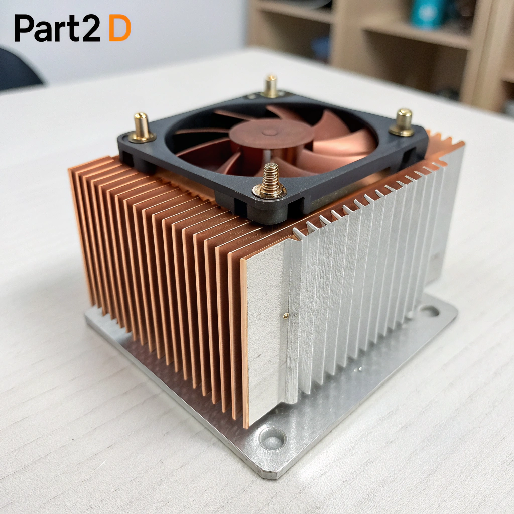
Hybride Entwürfe
- Kupfersockel + Aluminiumlamellen = bessere Leistung bei geringerem Gewicht
- Üblich in der High-End-Elektronik
-
Wärmerohre und Dampfkammern
- Schnelle Wärmeübertragung mit minimalem Metallanteil
- Ersetzen oft dicke Sockel
-
3D-gedruckte Strukturen
- Gitter- oder Wabenformen verwenden
- Stark, leicht und individuell geformt
-
Oberflächenbeschichtungen
- Schwarze Eloxierung verbessert die Strahlung
- Nanobeschichtungen verringern den Oberflächenwiderstand
Zusammenfassende Tabelle
| Trend | Nutzen Sie |
|---|---|
| Geschnittene Aluminiumlamellen | Dünner, leichter, besserer Luftstrom |
| Dampfkammern | Wärmeverteilung mit weniger Masse |
| Hybride Werkstoffe | Kombinieren Sie Stärke und Kosten |
| 3D-gedruckte Waschbecken | Weniger Metall, individuelle Passform |
| Hochemissive Beschichtungen | Passive Kühlung verstärken |
Wir bieten jetzt dünnere kundenspezifische Profile, leichtere Aluminiumlegierungen und Oberflächenbehandlungen, die die Wärmeleistung erhöhen. Es geht nicht mehr nur um die Form - es geht um die Gesamteffizienz des Systems.
Bei leichtgewichtigen Kühlkörpern werden häufig abgeschrägte Rippen oder Dampfkammern verwendet, um Größe und Masse zu reduzieren.Wahr
Diese Methoden bieten eine große Oberfläche und eine schnelle Wärmeausbreitung mit weniger Material.
Dickere Kühlkörper sind immer besser als leichtere, unabhängig von der Anwendung.Falsch
Dickere Ausführungen können in modernen Systemen schwerer, sperriger und weniger effizient sein.
Schlussfolgerung
Die Wahl der richtigen Kühlkörperdicke bedeutet, dass Sie Ihre thermischen Anforderungen mit dem richtigen Material, der richtigen Form und dem richtigen Luftstrom in Einklang bringen müssen. Eine zu große Dicke verschwendet Platz und Gewicht. Zu dünn riskiert Überhitzung. Mit neuen Materialien und intelligenteren Designs ist es jetzt möglich, Hochleistungselektronik effizienter und kompakter als je zuvor zu kühlen.
