
How to make an aluminum PCB enclosure?

I know finding a clear guide to make an aluminum PCB enclosure is hard. You need a step-by-step walkthrough.
You can learn how to pick dimensions, use tools, manage heat, and finish the enclosure clearly.
Let me lead you from concept to finished product.
What dimensions are essential when designing an aluminum PCB enclosure?
I first define PCB size and internal space. I also add room for mounting, connectors, and airflow.
Essential dimensions include PCB footprint, wall thickness, clearance, and mounting hole layout.
Dive deeper
When I design an aluminum PCB enclosure, I start by confirming the PCB dimensions. That includes board length, width, and height with mounted components. I always add at least 2–3?mm clearance on all sides. This avoids interference and ensures easy insertion and removal.
Then I decide wall thickness. For small enclosures, 1.5–2mm walls give enough strength. Larger boxes may need 3–4?mm. Thicker walls add rigidity but increase weight and cost. I balance strength and material use by analyzing enclosure size and application.
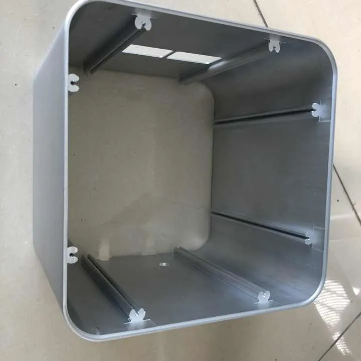
Next, I design internal mounting features. I add boss mounts or threaded standoffs aligned with PCB mounting holes. I make sure mounting bosses have 30–40% of the wall thickness in length for strong grip. For example, if walls are 2mm thick, I make bosses 6–8?mm tall to hold screws securely.
I also add cutouts for connectors, cables, switches, and display openings. I measure connector specs and leave 1?mm clearance around each hole. This makes insertion easier and prevents metal contact.
Then I allow space for thermal pads or airflow channels. If there are heat-generating chips, I leave room above the PCB for airflow or a heat spreader.
Finally, I design external dimensions, considering mounting feet or flange for panel mounting. If the enclosure will be wall-mounted, I add flanges extending past the box by 5–10?mm and hole patterns for screws.
Here is a summary of essential dimensions:
| Feature | Recommended Dimension |
|---|---|
| PCB clearance | PCB size + 2–3?mm each side |
| Wall thickness | 1.5–4?mm depending on size and use |
| Boss mount height | 3× wall thickness |
| Connector cutouts | Part spec + 1?mm clearance |
| Flanges/feet | Extend 5–10?mm beyond enclosure |
| Clearance type | Purpose |
|---|---|
| Lateral clearance | Prevent board or cables from rubbing on walls |
| Height clearance | Allow room for tall components and airflow |
| Mounting clearance | Ensure screws and stands can secure PCB safely |
This careful dimension planning avoids common mistakes like boards that don’t fit after coating or cutout misalignment. I always double-check against component datasheets and manufacturing tolerances before finalizing the design.
Boss mount height equal to wall thickness is sufficient.False
Boss mounts should be taller (about 3× wall thickness) for proper thread engagement.
Adding 2–3?mm clearance around PCB prevents interference.True
It ensures the board fits comfortably and allows for tolerances.
Which tools and machines are used to manufacture PCB enclosures?
I use CNC mills, drill presses, saws, and finishing tools. For production runs, we may add EDM, stamping, or extrusion.
Common machines include CNC milling, laser cutting, saws, tapping machines, and surface finish equipment.

Dive deeper
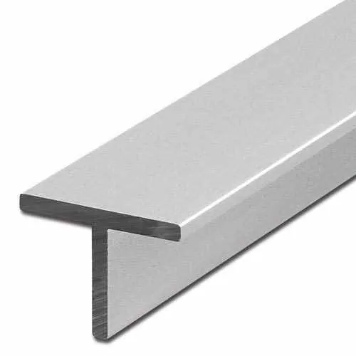
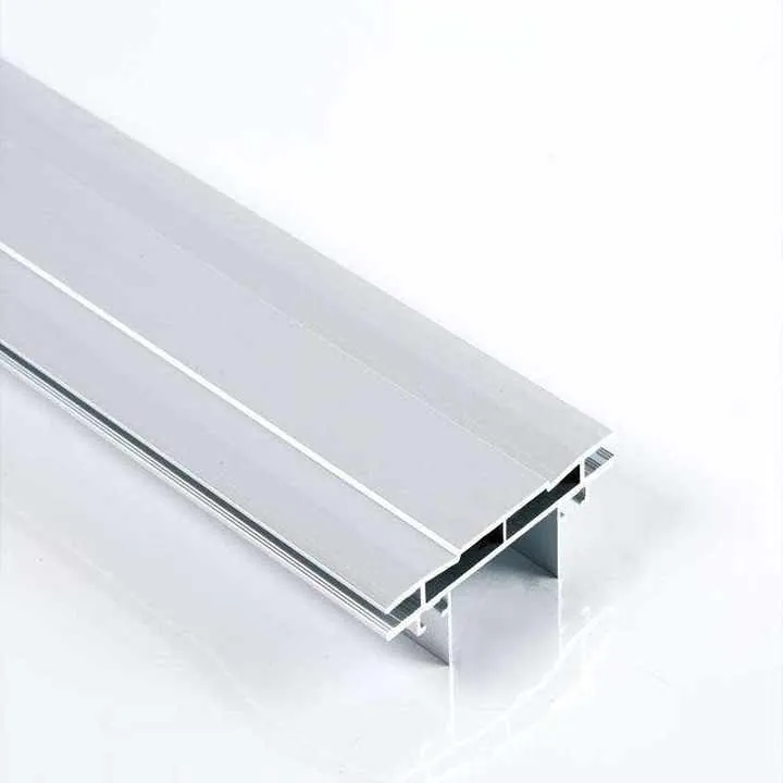
To make aluminum PCB enclosures, I often start with raw sheets or extruded profiles.
If I use aluminum sheet, I cut it to shape using a band saw, panel saw, or laser cutter. Laser cutting works well for precision and smooth edges. For extrusion, I cut extruded bars to length on a saw.
The next step is milling. I use a CNC mill to shape the enclosure. I secure the part in a vise or fixture. Then I perform operations:
- Face milling for flat outer surfaces
- Pocket milling for internal clearance zones
- Cutting off lids or flanges
- Adding boss mounts and standoff features
- Drilling holes for screws, connectors, and vents
Typical CNC machines are 3-axis mills, though 4-axis offers more flexibility for curved shapes.
After CNC, I tap threaded holes. I use a tapping machine or manual taps. I ensure bosses are straight and clean.
If I need ventilation slots or cutouts, I use either CNC or laser or punch tools. Laser cutting gives clean edges but may need bevel edge cleaning.
For tougher shapes, I may use wire EDM to cut precise profiles or internal slots. EDM is slower but precise to ±0.01?mm.
Then I check fit with the PCB. I insert the board, test screws, and connectors. If needed, I go back and adjust CNC code.
After manufacturing, I deburr edges using brushes, tumblers, or manual tools. Deburring prevents sharp edges harming PCBs or users.
For higher volume, stamping or extrusion plus CNC finishing is faster. I extrude U? or L?shaped sections and add CNC features. This combines efficient forming with precision tooling.
Then I may add tapping, countersinks, or standoffs in secondary machines. Finally I log machine settings and setup time, so next runs are consistent.
Here is a tool list:
| Tool/Machine | Purpose |
|---|---|
| CNC mill | Shape enclosure faces, pockets, and bosses |
| Laser cutter | Cut sheet panels or cutouts with precision |
| Saw (band or panel) | Cut raw aluminum to rough size |
| Wire EDM | Cut precise internal slots and intricate profiles |
| Tapping tools | Add threads to bosses or holes |
| Deburring tools | Smooth edges and prevent burrs |
| Production method | Best use case |
|---|---|
| CNC from billet | Low to medium volume, high precision |
| Extrusion + CNC | Medium volume, standard profile designs |
| Stamping + bending | High volume, simple box shapes |
I make sure operators follow tool parameters. For example, aluminum clears with 3,000 RPM and carbide endmills. If speed is wrong, the cutter may chatter or gum up. I log settings for part traceability.
This tool chain ensures each part is accurate, repeatable, and safe for PCB use.
Laser cutting is slower than CNC milling on aluminum.False
Laser cutting is often faster and gives cleaner edges, though costs vary.
Wire EDM can achieve accuracy of ±0.01 mm.True
Wire EDM is known for high precision in intricate cuts.
How do you ensure heat dissipation in aluminum PCB enclosures?
I use thermal conduction, expand surface area, and add airflow. I also rely on thermal interface materials (TIMs).
Good heat management uses enclosure walls, fins, pads, vents, or fans to move heat away from PCB.
Dive deeper
Aluminum is a good conductor of heat. To manage heat effectively, I design direct thermal paths from hot components to the enclosure walls. This means placing a chip right next to a metal wall or using thermal pads to bridge the gap.
I often include internal heat spreaders: flat plates or walls inside the enclosure in direct contact with the PCB, then coupled to outside surface. I machine these into the back panel or lid. I apply a thermal grease or adhesive for contact.
When natural convection isn’t enough, I add fins or vents. Fins increase surface area to help cooling. I design vents in the top and bottom panels to allow air to flow. Air flows in through bottom, rises as it warms, and exits top vents.
If the device runs hot or in closed spaces, I integrate a small fan. I cut mounting holes for fans or blowers. I add mesh or grill for protection and airflow channels to guide air across hot zones.
Thermal simulations help me check heat paths and get steady-state temperature. I adjust wall thickness, fin design, and vent size to maintain target PCB temperature.
I also consider paint or finish. Anodizing may reduce heat transfer slightly, but only by a few percent. Paint may reduce heat transfer more. So I place heat-critical paths first, then add finish only where needed, or leave parts uncoated.
For testing, I run a thermal loading test. I power the PCB at max load and record temperatures at key points using sensors. I check against design limits (typically <85?°C for many components). If temps are too high, I redesign with better conduction or more airflow.
I log thermal data and report it with the part. This helps clients verify performance before shipment.
Here is a summary:
| Heat path | Design approach |
|---|---|
| Conduction | PCB to metal wall via thermal pad/grease |
| Convection | Vents or fans for airflow |
| Spreaders/fins | Internal or external to increase dissipation |
| Surface finish | Avoid coatings that reduce heat transfer |
| Testing method | Purpose |
|---|---|
| Thermal simulation | Model steady-state temperature under load |
| Thermal test | Measure actual temperature under real conditions |
By focusing on these methods, I make sure the enclosure keeps electronics cool, reliable, and safe.
Anodizing greatly increases heat dissipation.False
Anodizing adds minimal thermal resistance and does not improve heat transfer significantly.
Thermal pads help transfer heat from PCB to enclosure.True
They fill air gaps and create conduction paths for heat.
What finishing options are best for aluminum PCB enclosures?
I choose coatings based on appearance, durability, and EMI needs. I offer anodizing, powder coat, brushed, or EMI gaskets.
Finishing options include anodizing, powder coating, brushed finish, painting, and EMI shielding treatments.

Dive deeper
Finishes protect aluminum and improve look. I start with anodizing. This electrochemical process creates oxide on the metal surface. It offers corrosion protection and natural metallic look. I pick Type II for standard use or Type III (hard anodize) for wear resistance. I can add dyes (black, silver, blue) for aesthetic or coding purposes.
Then I offer powder coating. This is a thicker colored finish applied as dry powder, then baked. It offers durable color and good corrosion resistance. Powder coat is ideal for outdoor or industrial use. But it adds thickness (30–60?μm) and reduces thermal conduction slightly.
For a raw metal look, I use brushed finish. I polish with abrasive belts, then anodize or clear coat. This gives a clean, textured appearance. Brushed finish doesn’t hide machining marks well, so parts must be machine?friendly.
If EMI shielding is required, I add an inner conductive paint or use aluminum foil gaskets around seams. I can also omit paint on mating surfaces to allow metal?to?metal contact.
I use painting (liquid spray) for low-volume color or specific RAL colors. It gives flexibility but may be less durable than powder.
I often combine finishes: for example, brushed finish for visible lid and anodize interior. Or powder coat exterior and raw aluminum interior for conduction.
Here is finish comparison:
| Finish Type | Pros | Cons |
|---|---|---|
| Anodizing (Type II) | Durable, natural look, good corrosion | Limited color, slight thermal barrier |
| Hard Anodize (III) | Very tough, wear resistant | Costlier, limited colors |
| Powder Coat | Multiple colors, thick, durable | Thick finish, slight thermal insulation |
| Brushed + clear | Natural texture, modern look | Shows machining marks, needs clear coating |
| Liquid paint | Custom color, flexible application | Less durable than powder |
| EMI option | Use case |
|---|---|
| Conductive paint | Shield interior for RF sensitive devices |
| Aluminum gaskets | Seal seams and prevent RF leaks |
| Bare mating surfaces | Metal-to-metal contact for grounding |
I publish finish specs for clients. This includes thickness, color code, hardness, and conductivity. I also send sample parts for approval before full runs.
That ensures the enclosure looks right, lives long, and meets EMI standards if needed.
Powder coating improves thermal conductivity.False
Powder coating adds an insulating layer and slightly reduces conduction.
Hard anodize gives better wear resistance than standard anodize.True
Type III anodizing produces a thicker, harder oxide layer suited for abrasive wear.
Conclusion
We covered key enclosure dimensions, tools, heat design, and finish options. You can now design and make enclosures that protect PCBs well.
If you want help on CNC machining, thermal layout, or finishes, I can guide you through each step.

