
Kuidas valida kõrgsagedusliku võimsuselektroonika jaoks jahutusradiaatorit?
Paljud jõuelektroonikasüsteemid ebaõnnestuvad soojusjuhtimise tõttu - olen näinud, kuidas seadmed põlevad läbi ja terved konstruktsioonid lammutatakse lihtsalt soojuse alahindamise tõttu.
Kõrgsagedusliku võimsuselektroonika jaoks õige jahutuselemendi valimine tähendab, et tuleb mõista lülituskäitumist, soojuskadusid, õhuvoolu ning kasutada õigeid materjale ja kujundeid, et hoida temperatuuri kontrolli all.
Selles artiklis selgitatakse, mis on kõrgsageduslik võimsuselektroonika tegelikult, miks termiline disain on kriitiline, kuidas ma valin õigeid jahutusaluseid ja millised suundumused seda valdkonda praegu kujundavad.
Mis on kõrgsageduslik võimsuselektroonika?
Kaasaegsed muundurid lülituvad nii kiiresti, et isegi väike induktiivsus ja mahtuvus võivad kogu süsteemi tasakaalust välja viia.
Kõrgsageduslik võimsuselektroonika viitab süsteemidele, mis töötavad tavapärasest 50-60 Hz tunduvalt kõrgemal, tavaliselt sadade kilohertside ja mitme megahertsi vahemikus, kasutades SiC- või GaN-lüliteid.

Minu projektides tähendab kõrgsagedus tavaliselt lülitamist 100 kHz kuni mitme MHz. Need sagedused võimaldavad väiksemaid induktoreid ja kondensaatoreid, mis aitab vähendada üldist suurust. Kuid need tekitavad ka rohkem lülituskadusid. See soojus koguneb kiiresti ja väiksemas ruumis, nii et jahutamine muutub raskemaks.
Kõrgsagedusmuundurid kasutavad kiireid pooljuhte, nagu MOSFETid, IGBTd ja eriti SiC- või GaN-seadmeid. Need tekitavad kiire pinge- ja voolumuutuse tõttu kiiresti soojust, mis on tingitud järskudest üleminekutest. See nõuab paremaid jahutusradasid kiibilt õhku.
Samuti on nende süsteemide sees vähem ruumi suurte jahutusradiaatorite jaoks. Kui sagedus tõuseb, kahanevad seadmed ja passiivsed komponendid muutuvad väiksemaks. Kuid kogu soojus ei vähene, vaid sageli suureneb. Seega peavad jahutusradiaatorid muutuma kompaktsemaks, kuid tõhusamaks.
Siin on neli asja, mida ma selliste süsteemide hindamisel kontrollin:
Sagedusvahemik
| Konverteri tüüp | Tüüpiline sagedus |
|---|---|
| Madalpinge DC/DC | 200 kHz - 2 MHz |
| Keskpinge inverter | 10 kHz - 100 kHz |
| GaN-põhine PFC | 1 MHz - 3 MHz |
| Uurimisprototüübid | Kuni 10 MHz+ |
Disainiga seotud probleemid
- Lülituskadu kasvab sagedusega.
- Paigutus peab minimeerima parasiitide teket.
- Jahutus peab toime tulema kiirete termiliste muutustega.
- Ühendustemperatuur peab jääma alla 125-150 °C.
Need seadmed ei saa endale lubada kuumaläbisid või aeglast soojuse hajumist. Seepärast nõuavad kõrgsagedussüsteemid juba algusest peale spetsiaalset soojusdisaini.
Kõrgsagedus tähendab võimsuselektroonikas tavaliselt lülitussagedusi üle paarisaja kilohertsini.Tõsi
Tööstuse dokumendid viitavad kõrgsageduslikule (HF) võimsuselektroonikale ~3 MHz ja kõrgemal.
Kõrgsagedus mõjutab ainult trafo suurust ja ei mõjuta jahutusradiaatori konstruktsiooni.Vale
Suurem lülitussagedus suurendab kadusid, termilisi üleminekuid ja mõjutab jahutusnõudeid.
Millised eelised tulenevad nõuetekohasest soojusdisainist?
Toitemooduli ülekuumenemine võib tappa selle kiiremini kui mis tahes elektriline viga - olen näinud täiesti häid konstruktsioone, mis on halva jahutuse tõttu hävinud.
Hea termiline disain pikendab eluiga, parandab tõhusust, takistab termilist läbikukkumist ja võimaldab ohutut tööd stressi korral.
Ilma nõuetekohase jahutuseta võib kõrgsageduslik seade saavutada oma termilise piiri ja lülitub välja. Veelgi hullem, see võib järk-järgult laguneda, mis viib varajase rikke tekkimiseni.
Õige jahutuse eelised
-
Pikem seadme eluiga
Kuumus vähendab kasutusiga. Pooljuhtide kulumine kiireneb iga kraadiga, mis ületab spetsifikatsiooni. Isegi 10 °C rohkem võib vähendada eluea poole võrra. -
Stabiilne töö
Kui liitumistemperatuur jääb madalaks, jäävad elektrilised parameetrid stabiilseks. Termiline triiv puudub. Ei ole ootamatuid väljalülitusi. -
Suurem tõhusus
Jahedamad komponendid kulutavad vähem energiat. Madalama temperatuuriga vähenevad nii juhtivuse kui ka lülituskadusid. -
Väiksem vormifaktor
Tõhus jahutus võimaldab kompaktsemaid süsteeme. Varakult planeerituna saab jahutusradiaatorid paremini integreerida. -
Parem ohutus ja sertifitseerimine
CE, UL ja muudele nõuetele vastavuse tagamiseks on nõutav termiliste spetsifikatsioonide täitmine. Nõuetekohane jahutus väldib ka põletusi, tulekahjuohtu ja elektrikatkestusi.
Tabel: Seadme jõudlus sõltuvalt temperatuurist
| Liitumise temperatuur | Mõju |
|---|---|
| < 100°C | Stabiilne jõudlus |
| 100°C - 125°C | Alusta derating |
| > 125°C | Kõrge ebaõnnestumise risk |
| > 150°C | Ületab spetsifikatsiooni - tõenäoline püsiv kahjustus |
Seepärast käsitlen ma jahutusradiaatori valikut kriitilise, mitte valikulisena.
Õige termiline disain võib võimaldada suuremat võimsustihedust kõrgsageduslikus jõuelektroonikas.Tõsi
Temperatuuri madalal hoidmisega saate kasutada väiksemaid komponente ja hallata kadusid, toetades suuremat võimsustihedust.
Kui kõrgsageduslik seade töötab veidi kuumemal kui selle nimiväärtus, ei mõjuta see selle kasutusiga.Vale
Kõrgemad liitumistemperatuurid või suurem termiline tsüklilisus vähendavad kasutusiga ja töökindlust.
Kuidas valida kõrgsageduslike seadmete jaoks jahutusradiaatorit?
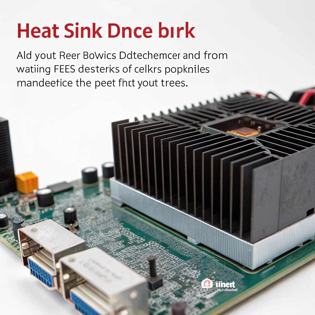
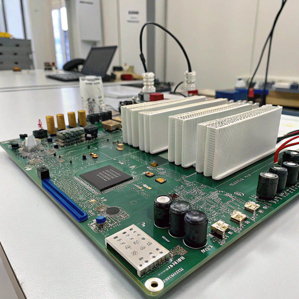
Hea jahutusradiaator ei ole lihtsalt lamellidega metallplokk - see on osa elektrisüsteemi õnnestumisest või ebaõnnestumisest.
Te peate sobitama termilise jõudluse tegeliku energiakadu, ruumi, õhuvoolu ja liidese takistuse - mitte arvama suuruse või kuju järgi.
Siin on minu täpne protsess jahutusradiaatorite valimiseks:
1. samm: Määrake soojuseelarve
- Võimsuskadu (Pd) - tavaliselt 10-100W väikeste moodulite puhul, 500W+ suurte muundurite puhul.
- Ümbritseva õhu temperatuur (Ta) - halvimal juhul. Sageli 40-50 °C.
- Max Junction Temp (Tj_max) - nt 150°C.
- Liidesetakistus - korpuse ja valamu vahel.
- Arvutage lubatud valamu ja õhu vaheline soojustakistus (RθSA):
[
R{\theta SA} = \frac{Tj{max} - Ta}{Pd} - R{\theta JC} - R_\theta CS}
]
2. samm: valige õige materjal
| Materjal | Juhtivus | Kulud | Kaal |
|---|---|---|---|
| Alumiinium | Hea | Madal | Valgus |
| Vask | Suurepärane | Kõrge | Raske |
| Hübriid | Tasakaalustatud | Keskmine | Keskmine |
Masstootmiseks kasutan tavaliselt anodeeritud alumiiniumi (6063-T5), sest see tasakaalustab kulusid, töötlemist ja soojapidavust.
3. samm: sobitamine õhuvoolu tüübiga
- Passiivne: kõrged lamellid, laiad vahekaugused loomuliku konvektsiooni tagamiseks.
- Sunnitud: tihedamad ribid, õhuvoolu spetsiifiline disain.
- Vedelikjahutusega: >500W või kompaktsete süsteemide jaoks.
4. samm: mudel või test
Kasutage simulatsioonivahendeid või ehitage prototüüp. Mõõtke termopaaridega koormuse all. CFD aitab visualiseerida kuumad tsoonid ja kinnitada teie matemaatikat.
Samm 5: Geomeetria sobitamine reaalsete piirangutega
- Uime kõrgus, paksus, vahekaugus.
- Paigaldusmeetod.
- Orienteerimine - vertikaalne annab parema konvektsiooni.
- Pindala vs jalajälg.
6. samm: Täpsustage selgelt
| Parameeter | Kirjeldus |
|---|---|
| RθSA Eesmärk | °C/W väärtus, mida peate täitma |
| Mõõtmed | Maksimaalne lubatud suurus |
| Paigaldusavad | Paigutus, vahekaugus |
| Lõpeta | Anodeerimine, pulbervärvimine jne. |
| MOQ | Põhineb ekstrusioonikonstruktsioonil |
Halb termiline liides või halb õhuvool tapab hea jahutuselemendi. Ma ei jäta kunagi vahele kontaktrõhu spetsifikatsioone või termopasta soovitusi.
Jahutusradiaatori valimiseks on vaja ainult vaadata selle mõõtmeid ja jätta õhuvool tähelepanuta.Vale
Õhuvool ja paigaldus mõjutavad oluliselt soojustakistust; õhuvoolu eiramine võib viia alakaalulise jahutuseni.
Valamu termiline takistus valamu ja ümbritseva keskkonna vahel (RθSA) on mõõtmise võtmeparameeter.Tõsi
Pärast seadme ja liidese takistuste arvessevõtmist peab neeldaja→ümbruse tee vastama järelejäänud soojuseelarvele.
Millised suundumused mõjutavad võimsuselektroonika jahutusradiaid?
Seadmed kahanevad ja lülituvad üha kiiremini - ma olen viimase aasta jooksul pidanud mitu jahutusradiaatorit ümber projekteerima, et sellega sammu pidada.
Uued pooljuhid, kõrgemad sagedused, väiksemad pindalad ja kõrgemad tõhususe eesmärgid sunnivad muutma jahutusmaterjale, -kujusid ja -tehnikaid.
Siin on see, mida ma praegu turul näen:
1. Laialibandilised pooljuhid
GaN ja SiC lülituvad kiiremini, tekitavad rohkem soojust ruutmm kohta ja vajavad rangemat termilist kontrolli. GaN-transistorid vajavad eriti madala induktiivsusega ja suure tõhususega jahutusradasid.
2. Vedelikjahutus
Kui võimsustihedus suureneb, lähevad mõned süsteemid üle külmadele plaatidele või mikrokanaliga vedelikupesadele. Olen tarninud profiile, mis saavad selleks külmadeks plaatideks töödeldud.
3. Hübriidsed jahutusradiaatorid
Alumiiniumist ribadega vaskpõhi on muutumas üha tavalisemaks. See levitab soojust kiiresti, hoides samal ajal üldist kaalu madalal.
4. Komplekssed geomeetrilised vormid
Mõnes konstruktsioonis kasutatakse viirutusribasid, volditud ribasid või aurukambreid. Olen näinud topoloogiliselt optimeeritud struktuure, mida ei saa teha ekstrusiooni teel - need on CNC või additiivselt valmistatud.
5. Pinna parandused
Anodeeritud, soonitud või kaetud ribid parandavad soojusülekannet. Paljud kliendid küsivad nüüd emissioonivõime suurendamiseks musta anodeerimist.
Siin on kokkuvõte:
| Trend | Mõju jahutusradiaatorite projekteerimisele |
|---|---|
| GaN / SiC kasutuselevõtt | Vajalik madalam RθJA, tihedam pakendamine |
| Kõrge võimsuse tihedus | Väiksemad ja tõhusamad valamud |
| Vedelikjahutus | Rohkem külmad plaadid ja kanalid |
| Uued tootmismeetodid | Additiivsed ja CNC-meetodid, mida kasutatakse koos ekstrusiooniga |
| Kohandatud pinnaviimistlus | Veel anodeerimine, pihustamine, markeerimine |
See maastik areneb kiiresti. Sinoextrud kohaneb sellega, pakkudes kohandatud profiile, paremaid pinnavõimalusi ja kiiret prototüüpimist.
Vedelikujahutus ja mikrokanaliga jahutusradiaatorid muutuvad üha levinumaks suure võimsusega ja kõrgsageduslikus elektroonikas.Tõsi
Hiljutine kirjandus näitab, et mikrokanaliga jahutusradiaatorid on traditsioonilistest õhkjahutusega jahutusradiaatoritest paremad ja vedelikjahutus on tulevikutrend.
Traditsioonilised suured alumiiniumist soojusalvestid jäävad ainsaks jahutuslahenduseks kogu võimsuselektroonika jaoks.Vale
Jahutusmeetodite areng ja suuremad jõudlusnõuded tähendavad, et üha enam on vaja alternatiivseid jahutuslahendusi.
Kokkuvõte
Õige jahutusradiaator muudab teie kõrgsagedusliku võimsusdisaini või katkestab selle. Sobitage see oma termilise eelarve, süsteemi vajaduste ja jahutusmeetodiga - või riskige, et soojus rikub kõik.


