
Hliníkový výlisek pro chladiče LED?

LED lights run hot. Overheating can shorten life and change color. Many designs fail to move heat away fast enough. The right heat sink can fix that.
Aluminum extrusion is ideal for LED heat sinks because it offers high thermal conductivity, allows custom shapes with fins for better cooling, and remains lightweight and cost‑effective under mass production.
This article explores why aluminum extrusion works so well. Then it shows how to design fin shapes, avoid thermal limits, and use airflow wisely. You will learn what makes an extrusion design good for LED cooling.
What makes aluminum extrusion ideal for LED cooling?
Hot LED pots sound alarm. LED makers worry about heat buildup, poor heat paths, and heavy heatsinks. Bad design leads to short life or burnt lights.
Aluminum extrusion is perfect because it moves heat quickly, lets designers make many cooling shapes, and stays light so fixtures remain easy to install.

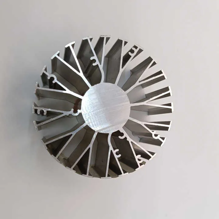
Many things make aluminum extrusion good for LED fixtures. First, aluminum has high thermal conductivity compared to many materials. It can pull heat away from LED chips fast. Then it spreads heat along the extrusion body. That avoids hot spots and keeps LED temperature under control. Second, extrusion is a flexible process. Designers can push or pull aluminum through a shaped die. That creates long bodies with complex cross‑sections. Fins, hollow parts, mounting holes all become possible at one pass. This flexibility allows one to design the exact shape needed for a light fixture.
When LED modules run at hundreds of lumens, even small heat leaks matter. A thin sheet or stamped metal can only give so much surface area. Extruded fins add much more surface area compared to volume and help reject heat into air. Also surface finishing can improve thermal radiation or corrosion resistance. For example, anodized aluminum adds durability without hurting conductivity much. This matters if LED lights run outdoors. In short, aluminum extrusion combines strong heat flow, wide thermal paths, design freedom, and cost control.
Aluminum extrusion allows complex shapes to increase surface area for LED coolingPravda
Extrusion makes it easy to include fins and other structures that improve heat dissipation.
Steel is better than aluminum for LED cooling due to strengthFalse
Steel is stronger but has lower thermal conductivity and is heavier, making it less suitable for heat sinks.
Which fin configurations optimize heat dissipation?
Bad fin design kills good heat sinks. Some fins block air or sit too close. Others are too thin. Designers need right layout, fin shape, fin spacing. Wrong choices slow cooling and waste material.
The best fin configurations include many thin fins, spaced to allow airflow, with high surface‑area shape. That helps move heat from metal to air fast and steady.
Fin count, fin spacing and thickness
A good heat sink fin layout balances fin count, spacing, and thickness. If fins are too few or thick, you lose surface area. If fins are too many or too thin, air cannot flow and convection stalls. A mid‑range works best: many fins but parted enough for air to pass.
| Fin Layout Element | Effect on Cooling | Typical Range for LED Sinks |
|---|---|---|
| Tloušťka ploutví | Thicker fins store more heat but reduce surface area | 1.5 – 3.0 mm |
| Rozteč ploutví | Wider spacing allows airflow but reduces fin count | 3.0 – 6.0 mm between fin tips |
| Fin height above base | Taller fins increase area but add weight and size | 15 – 40 mm |
In a design I saw, using 2.2 mm thick fins spaced 4 mm apart gave better cooling than 3 mm thick fins spaced 2 mm apart. The airflow was better and surface area stayed high.
Fin shape and surface treatment
Fins do not have to be flat. Some designs use tapered fins. Others use curved or wave shapes. These shapes help disrupt air boundary layers. Disrupting boundary layers helps fresh air touch fin surfaces. That improves heat transfer to air. Also surface finish matters. A clean, anodized surface helps emissivity and resists corrosion. For outdoor LED lights, this helps lifetime.
Example: Comparison between two fin layouts
Here is a simple example. Suppose we have two extruded heatsinks of same base width and thickness. One has 10 fins spaced tight, the other has 6 fins spaced wide. With good airflow, the 6‑fin wide‑spaced design may cool better because airflow is not blocked. With poor airflow (like in enclosed fixture), the 10‑fin design may fail because air cannot enter fins.
This shows no one design suits all. Designer must match fin layout to air path and fixture type.
Many thin fins spaced moderately outperform fewer thick fins in LED heat sinks when airflow is goodPravda
Because thin fins increase surface area and moderate spacing allows airflow for convection.
The more fins always increases heat dissipation regardless of spacingFalse
If fins are too close air cannot flow properly and convection reduces, so many fins can worsen heat dissipation.
Are there thermal limits for LED applications?
LED heat sinks are powerful. But every design meets limits. If design ignores maximum temperature or thermal resistance, LED life suffers. Overcrowding heat sinks or running too high power kills long life or color stability.
Yes. LED heat sinks have limits: they must keep LED case temperature below rated max and dissipate wattage safely. Exceeding thermal limits causes failure and reduces lifespan.

Thermal resistance and junction temperature
Thermal performance of a heat sink is often given as thermal resistance (°C/W). This measures how many degrees Celsius the heat sink will rise per watt of heat. Suppose LED module gives 10 W heat. A thermal resistance of 5 °C/W means 50 °C rise. If ambient is 25 °C, LED case runs at 75 °C, perhaps too high. Lower thermal resistance is better.
| Heat Sink Thermal Resistance | LED Power | Expected Temperature Rise |
|---|---|---|
| 5.0 °C/W | 5 W | 25 °C |
| 5.0 °C/W | 15 W | 75 °C |
| 2.0 °C/W | 15 W | 30 °C |
For many LED chips maximum case temperature is 85–105 °C. So a heat sink must keep case under that at the hottest expected conditions. Designers often target thermal rise under 40–50 °C to be safe.
Contact resistance and mounting
Good thermal contact between LED module and base of extrusion matters a lot. Air gap or thin thermal pad may add resistance. Even a few tenths of degree per watt causes many degrees of extra heat under load. When extrusion is CNC machined flat base and module pressed with thermal paste or pad, contact becomes strong. When using stamped or rough base, contact suffers.
Also sometimes LED fixtures are enclosed. That kills convection. Then heat sink must be much larger or use active cooling. In sealed fixture, designers must calculate total heat and ensure sufficient surface area and airflow path or add vents or fans.
Exceeding thermal resistance limits in LED heat sinks can lead to overheat and reduce LED lifespanPravda
High thermal resistance means poor heat dissipation, which raises LED temperature beyond safe limit, shortening life.
As long as the heat sink is aluminum, there is no thermal limit for LED powerFalse
Even aluminum heat sinks have finite capacity; design matters and contacting and surface area must handle the heat load.
How is airflow considered in heat sink design?
Poor airflow spoils good heat sink design. Even excellent extrusion and fin layout fail if air stays still. Many LED lights live in enclosed housings or near walls. Without airflow, heat stays near fins. That causes heat buildup and reduces cooling.
Airflow matters a lot. Designers must match heat sink fins and fixture openings so air moves freely across fins and carries heat away quickly.
Air path and fixture design
Heat sink cannot work alone. The fixture must allow air to flow across fins. If fixture is sealed, designers must add vents or rely on convection path up or down. Designers must think where hot air goes. Usually hot air rises. So vents at top help. In outdoor LED street lights, overheated air must escape. Designers may add slots or louvers. Otherwise heat gets trapped and builds up.
Effect of airflow speed on cooling
Even small air flow helps. A fan or natural wind doubles or triples heat transfer compared to still air. Gentle breeze or small fan connector in fixture greatly adds cooling power. That means the same extrusion can cool higher power LEDs if air moves. Designers choose between bigger extrusion or adding airflow.
Example numbers (rough guide):
- Still air, small natural convection: heat sink lowers thermal resistance by maybe 30‑50%.
- Light airflow (0.5–1.5 m/s): heat transfer doubles vs still air.
- Strong airflow (3–5 m/s): cooling more efficient, fins stay near ambient.
Combined view: fin design meets airflow
When fins are dense and tall but airflow is weak, airflow stalls inside fins. Then effective area shrinks. If airflow is strong, tall dense fins work well. So design must consider both fin density and expected airflow. Many LED fixtures pick moderate fin density and rely on passive convection or small fan flow depending on fixture.
Even small forced airflow dramatically improves heat sink cooling performancePravda
Moving air sweeps away heat from fins faster than still air, increasing convection cooling.
Dense fin arrays cool better than sparse ones regardless of airflowFalse
Without airflow, dense fins block air flow and reduce effective cooling despite large surface area.
Závěr
Aluminum extrusion fits LED cooling needs well because it gives good heat flow, custom shape, light weight and easy production. Fin layout, thermal limits and airflow all matter. Good heat sink design balances them. Proper extrusion plus fins and airflow keep LEDs cool and long‑lasting.
