
Can a liquid‑cooling plate handle thermal stress?
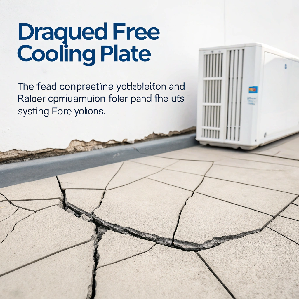
I recently faced a system failure where a cooling plate cracked under extreme temperature swings — that made me ask: can a liquid cooling plate really handle thermal stress?
Yes — a liquid cooling plate can handle thermal stress if designed correctly, but if it isn’t, thermal stress can cause fatigue, cracking, and performance loss.
In the rest of this article I’ll walk through what thermal stress means in cooling systems, why it causes performance loss, how to design plates for durability, and which new materials are improving stress tolerance.
What is thermal stress in cooling systems?
Imagine a metal plate being rapidly cooled by liquid while fixed in place — you’ll create internal strain and possible damage.
Thermal stress in cooling systems refers to mechanical stress inside materials caused by temperature changes that force constrained expansion or contraction.
When a component — say a cooling plate in a liquid loop — undergoes temperature changes, its material tries to expand (when heated) or contract (when cooled). If the plate is constrained (for example by welded joints, mounting screws, surrounding structures) or if there are temperature gradients across the plate (one side hot, one side cold), internal stress can build up.
In a liquid‑cooled plate scenario, the coolant might rapidly remove heat or introduce cold fluid, while the solid metal has to adapt. The mismatch in thermal expansion coefficient between the plate and the device it’s bonded to (or between different parts of the plate) causes local stresses.
Furthermore, if the plate surface is heated non‑uniformly (for instance some area near a chip hotspot, or uneven fluid flow) then one region expands more or sooner than another. That leads to internal tensile and compressive stresses.
In short: the material is being forced to take on strain it “wants” to take, but constraints or gradients stop “free” expansion/contraction, so stress builds. This is thermal stress.
Thermal stress occurs when temperature changes cause constrained expansion or contraction in materials.True
This is the definition of thermal stress in mechanical and cooling systems.
Thermal stress only happens when the material reaches its melting point.False
Thermal stress can occur at any temperature where expansion or contraction is restricted, not just at melting points.
Why does stress cause performance loss?
Stress might sound like a material issue only, but for cooling plates it ties directly into heat transfer, reliability, and service life.
Stress causes performance loss because deformation, loosening joints, cracks, delamination, or warping reduce heat‑transfer efficacy, introduce leaks or failure modes, and degrade durability.
When thermal stress accumulates, several negative things can happen in a liquid cooling plate system. Here are key failure or performance‐loss mechanisms:
Warping or distortion
If the plate deforms slightly under cyclic thermal loading, the contact between the heat source (for example a PCB, battery cell, or power module) and the plate may degrade. That reduces conduction from the source into the plate. Reduced conduction means higher junction temperature, less effective cooling.
Cracking or fatigue
Repeated thermal cycles (heating and cooling) cause fatigue in the material at points of high stress concentration (for example near joints, welds, corners). Cracks can form, which reduce structural integrity. If cracks propagate, fluid channels may leak or flow may change. Leaks cause catastrophic failure; changes in flow reduce heat transfer performance.
Delamination or joint failure
If the cooling plate is bonded or welded into a larger assembly (for instance joined to a baseplate or clamped to other parts), stress can cause the interface to degrade. Once the interface is compromised, thermal resistance increases. That means for the same heat load the temperature rises, reducing performance margin.
Reduced heat transfer coefficient
When material fatigue or distortion modifies channel geometry (for example slightly collapsing a microchannel or changing contact pressure), the coolant flow pattern and thermal contact degrade. That raises thermal resistance of the plate‐coolant system. Lower heat transfer means higher temperature rise, which can further accelerate stress – a vicious cycle.
Creep and long–term deformation
At elevated temperatures and sustained stress, materials may slowly deform (creep) even if stress is below yield. Over time the plate may sag, lose flatness, or otherwise change shape. This again reduces the thermal performance or may create fluid flow issues.
Cracks and warping in cooling plates reduce thermal performance.True
Structural damage like cracking or warping impairs thermal contact and coolant flow, which reduces efficiency.
Thermal stress increases thermal conductivity of a cooling plate.False
Thermal stress causes physical damage that reduces effective heat transfer, not improves it.
How to design plates for thermal durability?
Designing for durability means anticipating stress and eliminating or reducing its destructive paths ahead of time.
Good thermal‑durability design for cooling plates means selecting compatible materials, controlling temperature gradients, designing channel geometry and mounting to relieve stress, and validating fatigue life under cycling.
When I design a cooling plate (or oversee such design), I follow these key design principles:
Material and expansion compatibility
- Choose materials whose thermal expansion coefficients are compatible with the devices they cool and the mounting structures.
- Use metals with good thermal conductivity and mechanical strength for the expected loads.
Uniform temperature field
- Design flow channels and plate geometry to promote even cooling — avoid hot spots.
- Use simulation to identify gradients and stress points.
Mechanical mounting and constraint
- Allow for slight thermal movement. Avoid rigid fixation that locks all expansion.
- Use flexible gaskets or floating mounts where needed.
Channel geometry and wall thickness
- Thin walls reduce thermal gradients.
- Avoid sharp corners or welds in high-temperature areas.
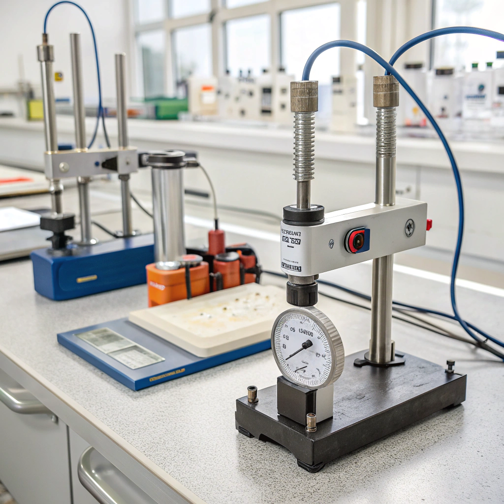
Fatigue and thermal cycling
- Design for the expected number of cycles.
- Test under real conditions if possible.
- Use models like σ = E α ΔT to estimate stress.
Interface and clamping
- Use clamps that maintain even pressure across temperature swings.
- Apply thermal paste or pad that resists degradation.
Cooling loop control
- Limit sudden changes in fluid temperature.
- Avoid cold shocks on a hot plate.
| Design Focus | Strategy |
|---|---|
| Thermal Compatibility | Match CTE with surrounding parts |
| Mechanical Design | Avoid overconstraint; allow movement |
| Flow Management | Promote even heat removal; avoid hotspots |
| Material Choice | Pick materials with good fatigue and conductivity |
| Interface Control | Maintain stable contact across thermal cycles |
Allowing slight thermal movement in mounting helps reduce stress on cooling plates.True
Allowing expansion or contraction prevents buildup of internal stresses that cause damage.
Thicker cooling plate walls always reduce thermal stress.False
Thicker walls can create higher thermal gradients, which may actually increase stress.
What new materials improve stress tolerance?
Classic aluminium or copper plates are good, but newer composite materials and processes push the envelope for durability and stress tolerance.
Advanced materials like metal‑matrix composites (e.g., AlSiC), high‑strength copper alloys (e.g., Glidcop), and improved brazed joints provide better thermal conductivity, matched expansion, and fatigue resistance for cooling plates.
Let’s look at some of the newer material options and what they bring in terms of stress tolerance for cooling plates.
AlSiC metal‑matrix composite
AlSiC combines aluminium with silicon carbide particles. It keeps good thermal conductivity but lowers thermal expansion. That means less mismatch when it’s bonded to chips or other parts. This helps avoid stress.
Glidcop copper alloy
This copper alloy holds up better under high heat. It adds tiny ceramic bits to stop the metal from getting soft. The result is stronger cooling plates that resist creep and last longer under cycling.
Copper vs Aluminum trade
Copper has higher conductivity and better stress tolerance. Aluminium is lighter and cheaper. If performance matters more than cost or weight, copper is often better.
Brazed or welded joints
Vacuum brazing makes joints strong and heat‑resistant. It avoids cracks and leaks. That helps plates survive long‑term use. Friction stir welding is another clean, strong option.
3D‑printed heat sinks
New printing tech lets engineers make complex cooling paths. Some designs use unusual shapes that spread heat better or handle expansion well. These are still rare, but promising.
| Material | Benefits for Stress Tolerance |
|---|---|
| AlSiC Composite | Lower thermal expansion, good conductivity |
| Glidcop Alloy | High strength at heat, resists creep and cracking |
| Standard Copper | Top performance, strong, expensive |
| Standard Aluminum | Light, cheap, but higher expansion and softer |
AlSiC composites reduce thermal expansion mismatch between cooling plates and devices.True
AlSiC is designed to match the expansion rate of sensitive electronics, reducing stress.
Standard aluminum always has better thermal stress tolerance than Glidcop.False
Glidcop is engineered for strength and stress resistance, making it better in thermal cycling.
Conclusion
In my experience, when a liquid cooling plate is properly designed for the expected thermal and mechanical loads, it can handle thermal stress effectively. The key is to understand how thermal stress arises, why it undermines cooling performance, and how to design and select materials to resist it. By applying good mechanical and thermal design, and choosing advanced materials when required, you can build durable, high‑performance systems with long service life.

