
How to design aluminum extrusion?
Are you frustrated when a sleek aluminum profile ends up costing too much or failing to deliver? Let’s fix that problem with smart design.
Yes — you can design aluminum extrusions that are efficient, manufacturable and cost‑effective by focusing on geometry, wall thickness, die flow and simulation for validation.
Below we explore four essential questions you should ask when designing your aluminum extrusion profiles. Each one digs deeper into a different aspect of the process so you can avoid common traps and design better from the start.
What factors shape extrusion geometry?
It is easy to overlook how the shape of a profile drives cost and manufacturability — this is a real pain point for many designers.
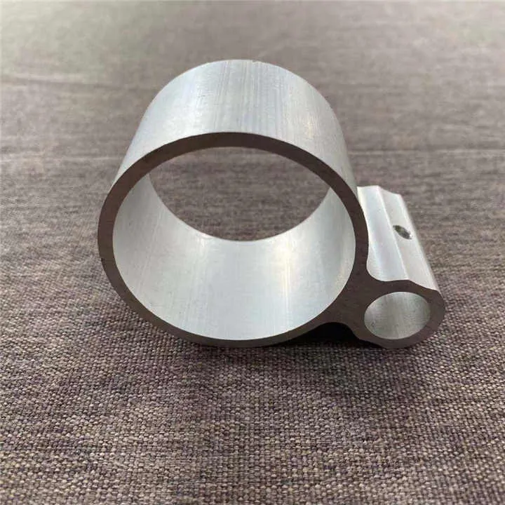
The cross‐section size, circumscribing circle diameter (CCD), perimeter/area ratio, shape complexity and symmetry all influence how easily an extrusion can be made.

When designing aluminum profiles, one of the first things to check is the size of the “smallest circle that will entirely enclose the cross‑section” (often called the CCD). The smaller the CCD, generally the more tools and press sizes that can handle it, which lowers cost and increases manufacturability.
Another important metric is the ratio of the cross‑section area to the total perimeter (sometimes called a “die difficulty factor”). The more perimeter for the same area, the harder the aluminium has to flow through the die and the more stress on the tooling.
Symmetry of the profile also matters — a shape with balanced walls, fewer asymmetries, and smooth transitions tends to extrude more reliably and produce fewer defects.
Some practical checks:
| Check | Why it matters |
|---|---|
| CCD under ~200–250 mm (or under ~8–10 in) | Many presses handle smaller circles more economically. |
| Low perimeter/area ratio | Lower ratio means less friction and easier flow. |
| Avoid long “tongues” or very narrow fins (high aspect ratio) | These tend to cause cooling/freezing issues or distortion. |
| Walls of similar thicknesses and smooth transitions between thick & thin | This reduces stress concentration and distortion. |
By focusing on these geometry factors early, you reduce the risk of tooling problems, production delays or higher cost. In my experience, when a designer reduces perimeter/area ratio and keeps thickness transitions gradual, the extrusion vendor can achieve better quality with fewer rejections.
Smaller CCD always means lower cost for all extrusions.False
Smaller CCD generally reduces cost but other factors (material, complexity, wall transitions, surface finish) also influence cost.
High perimeter/area ratio increases difficulty of extrusion.True
Higher perimeter relative to area increases surface contact and friction, making extrusion harder.
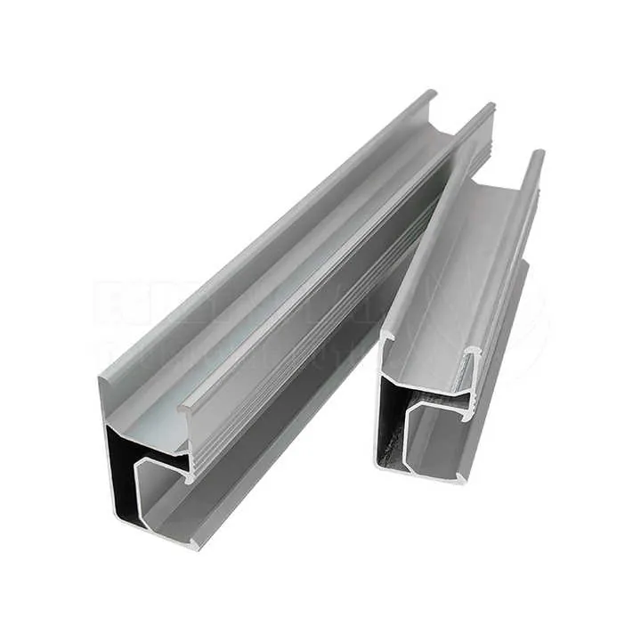
Why wall thickness influences manufacturability?
Wall thickness may sound like a minor detail, but it can make or break your extrusion process.
If you design wall thicknesses that are too thin, have big jumps between thick and thin sections or mix many disparate thicknesses, you increase risk of distortion, die wear and cost.

Wall thickness is a critical design variable for extruded aluminium profiles. If a wall is too thin it may cause issues with structural strength and may lead to excessive wobble during extrusion or downstream processes. On the flip side, making everything thick “just to be safe” may add unnecessary mass, cost and cooling problems.
One guideline: keep adjacent wall thicknesses fairly uniform. A large jump from a thick wall to a thin wall (for example 4 mm to 1 mm) creates stress concentrations during flow, cooling and solidification. Many manufacturers recommend wall‑thickness ratios (thick:thin) not exceeding about 2:1 or so in critical transitions.
Another point: minimum practical thickness depends on the profile size and complexity. Too thin and you risk “fish eyes”, warping or high scrap rates. Designing with realistic minimums ensures you don’t ask the process to do the impossible.
Table: Wall thickness design considerations
| Parameter | Guidance |
|---|---|
| Minimum wall thickness | Use vendor guidance — too thin = higher risk. |
| Thickness transitions | Use generous fillets/radii when going from thick to thin walls. |
| Uniformity across profile | Balanced walls make cooling and straightening easier. |
| Avoid extremely thin fins without support | Thin unsupported elements can distort or break. |
In practice, I have seen designs with very thin walls (<1 mm) that looked good on CAD but in extrusion resulted in large tolerances and high finish‑cost. When we adjusted the wall thickness upward slightly and added a rib for support, the cost dropped and straightening effort reduced. Good wall design is a win for cost, quality, and lead time.
Designing very thin walls always reduces cost.False
While less material may reduce raw cost, very thin walls increase risk of defects, reject rate and downstream cost.
Using fillets between thick and thin wall transitions improves manufacturability.True
Fillets reduce stress concentrations and help aluminium flow/smooth cooling.
How to optimize design for die flow?
The die flow path is invisible to many designers — yet it governs whether the part extrudes cleanly or causes trouble.
Optimising design for die flow means designing the profile and tooling such that material enters, flows and exits the die evenly, with balanced velocities, minimal dead zones and good thermal control.
When you push aluminium through a die, you want smooth, uniform flow. If the flow is uneven, you risk variations in wall thickness, surface defects, internal voids or excessive tool wear. That means the shape you design must support good die flow.
For example, using multiple “pockets” or stepped flow‑channels inside the die can distribute material more evenly, reduce dead‑metal zones and lower pressure.
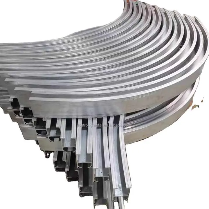
Similarly, simplifying the profile geometry helps: the more complex the cross‑section (many voids, narrow webs, high aspect ratio fins), the harder it is to design a die and manage flow. Simplification may cost some freedom of shape but will significantly reduce tool cost and manufacturing risk.
Some practical tips for die flow optimisation
- Use generous radii and smooth transitions in the profile so the aluminium doesn’t “pile up” or slow down in corners.
- Keep wall‑thickness changes gradual so flow speed stays consistent across the section.
- Avoid extreme thin fins or very deep cavities without supporting webs — these can cause “fish‑scales” or distortion post‑extrusion.
- Where possible, design the profile with symmetry so flow from the die can be balanced and the tool life is improved.
- Work with your extrusion partner early — die engineers may suggest adding a rib or changing a contour to improve flow and reduce cost.
From my experience working on aluminium profiles, when we made a minor change to reduce a long narrow fin and replaced it with a slightly wider rib, the extruder reported easier flow, higher speed and fewer rejects. It shows that flow optimisation often means “small shape changes = big process gains”.
Complex profile geometry always yields higher quality parts.False
While complex geometry may meet functional needs, it often increases tool cost, manufacturing risk and difficulty in die flow.
Balanced material flow in the die helps reduce defects and tool wear.True
Uniform flow decreases stress on the die and leads to more consistent extrudate quality.
Can simulation validate extrusion design?
You might think simulation is nice to have, but in extrusion design it is increasingly becoming essential rather than optional.
Yes — simulation (finite element analysis on material flow, heat transfer and deformation) lets you test die and profile designs virtually, catch issues early and save tooling/time cost.

Simulation tools (often using finite element methods) can model how aluminium will flow through a die, how temperature evolves during extrusion and how the profile might deform or warp after leaving the die. By simulating, you can spot potential hotspots, flow imbalances, and areas where the extrudate might deviate from design tolerances.
Further, simulation isn’t just about tool design; you can also simulate how the entire extrusion process plus cooling/stabilisation will affect the profile. That means you can refine your profile geometry (wall thicknesses, web sizes, transitions) before sending it to tooling.
Using simulation brings several advantages:
- Reduces number of die trials and prototyping cycles.
- Helps control cost and lead time by catching design issues early.
- Provides data you can share with your extrusion partner so they understand process limits.
For example, when we had a profile with a complex hollow section, we ran a flow simulation and discovered a dead‑metal zone near a thin web. We adjusted the web position and added a relief, and the simulation showed much better uniform flow and lower predicted pressure. Without simulation we would likely have had tooling issues and more scrap.
Of course simulation doesn’t replace collaboration with your extruder or hands‑on experience. But in high‑quality aluminium extrusion manufacturing, it is a powerful validation tool that I recommend you plan into your design process.
Simulation can completely replace physical trials in extrusion design.False
Simulation greatly reduces trials but cannot entirely replace physical tests and experience with tooling and process variations.
Flow and thermal simulation before tooling helps catch design issues early.True
Pre‑tooling simulation identifies flow imbalances, hot spots and geometry problems.
Conclusion
In summary, by paying attention to geometry, wall thickness, die flow and validation via simulation you significantly increase your chances of designing aluminium extrusions that deliver real value. Good design leads to lower cost, better quality and smoother production.

