
How does channel design affect liquid cooling plate flow?
I see the problem: uneven coolant flow in a liquid cooling plate creates hot spots and wasted capacity.
Channel design in a liquid cooling plate directly impacts how uniformly fluid flows, how much pressure drop occurs, and how effectively heat is removed from the surface.
I’ll walk you through what channel design means, why geometry matters, how to design for better flow uniformity, and the latest trends so you can apply it in your aluminium‑extrusion / cold‑plate business.
What is liquid cooling channel design?
When I first started looking at cold‑plates I realised many engineers just treat the internal channels as generic – but they are not.
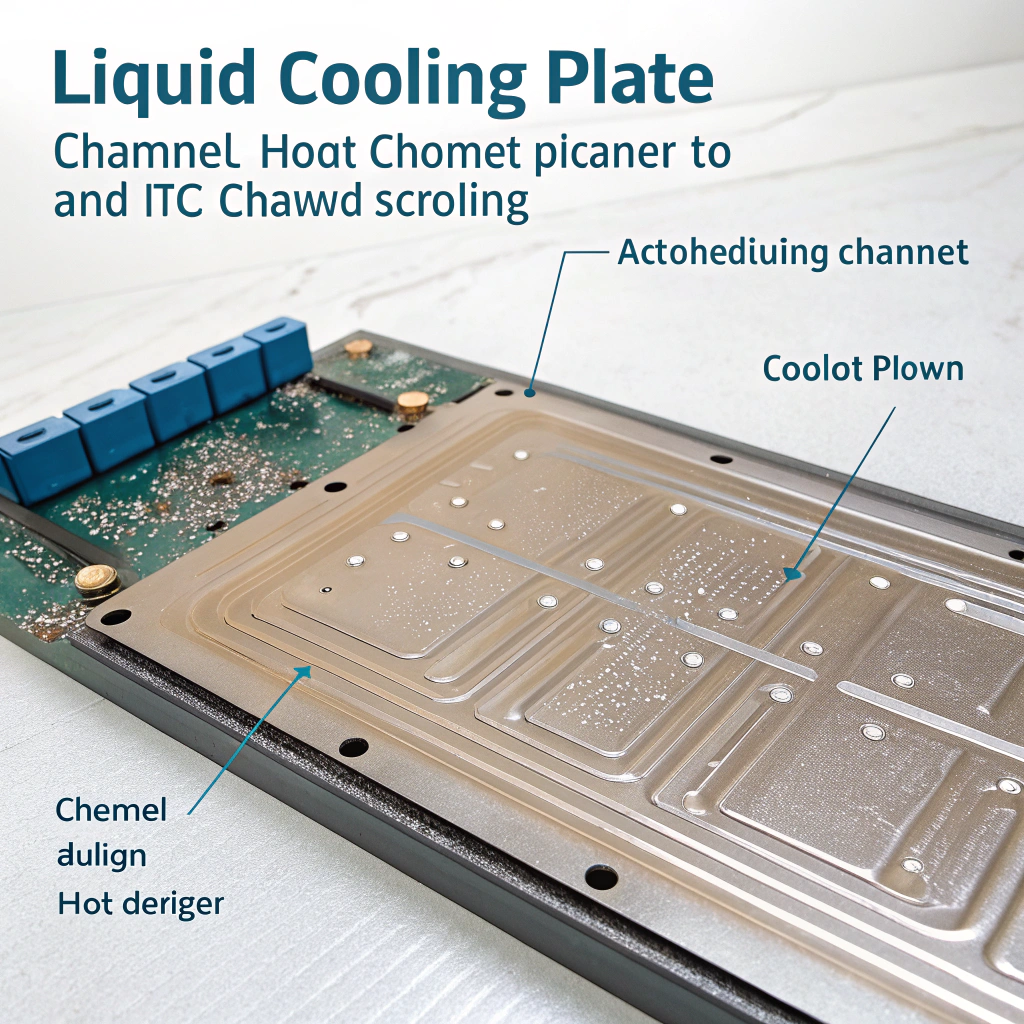
Liquid cooling channel design refers to the layout, shape, size, and arrangement of the liquid passages inside a cooling plate (cold plate) that guide the coolant from inlet to outlet and across the surface being cooled.
In more detail, channel design means the path the coolant takes inside the cold plate: is it a single serpentine channel, parallel channels, spiral, or a combination of manifold plus branches? It also includes the cross-section of each channel: its width, height, shape, and spacing, as well as how the coolant enters and exits the plate.
From the perspective of your business, channel design influences how easy a plate is to manufacture, how much it costs, how reliable it is, and how it performs in terms of flow and heat transfer. Some designs can be directly extruded, while others require CNC machining or brazing. Good channel design balances the need for uniform cooling and low pressure drop. If channels are too narrow, pressure drops. If they’re too wide or spaced too far, heat removal becomes uneven.
The internal channels also impact how well the fluid spreads across the entire cooling surface. Poorly designed channels may leave areas with little flow, causing hot spots. Proper design ensures coolant flows evenly and efficiently, maximizing thermal performance while keeping costs and manufacturing complexity under control.
Channel design only affects how fast the coolant travels, and has no impact on temperature uniformity on the plate surface.False
Channel design affects not just flow rate, but how uniformly coolant covers the surface, which in turn affects temperature uniformity.
Channel design refers to the layout, size and shape of passages inside the cooling plate that guide the coolant.True
That is exactly the definition of channel design for liquid cooling plates.
Why does channel geometry influence flow?
It bothered me that two identical cold plates could behave so differently — the secret was in the geometry of the channels.
Channel geometry (shape, cross-section, length, spacing, inlet/outlet layout) influences fluid velocity, pressure drop, flow distribution among branches, thermal boundary layers, and heat transfer coefficients — and so determines how the fluid flows and how well the plate cools.
Here’s how geometry makes a difference:
Cross-section and size
A narrow channel speeds up the flow, creating more turbulence and improving heat transfer, but it also increases resistance. Wider channels reduce pressure drop but slow down the coolant, reducing thermal efficiency. There’s a balance between speed, heat absorption, and pressure.
Channel path and length
Longer or winding paths increase pressure drop and may cause the coolant to warm before reaching the far end, reducing performance. Sharp turns or dead-ends can also cause flow separation and uneven cooling.
Parallel branches
In plates with multiple parallel channels, uneven distribution can occur if branches are not designed to balance flow. If one branch gets more flow, it cools better than others. Equal length and cross-section for all branches help avoid this problem.
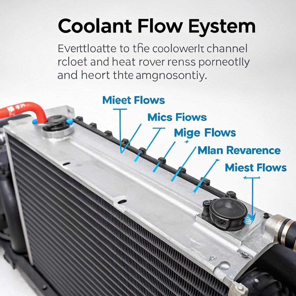
Inlet and outlet placement
If the coolant enters at one corner and exits at the opposite, areas near the outlet may receive warmer coolant. Placing the inlet near the center or using multiple inlets/outlets can improve distribution.
Channel spacing
Channels that are too far apart may leave hot zones in between, while tightly spaced channels improve uniformity but may cost more or be harder to manufacture.
Flow disturbances
Fins, grooves, or other features inside channels increase mixing and heat removal. However, they also increase friction and require more pump power.
Together, all these geometric features affect how well the coolant flows and how evenly it removes heat. That’s why even small changes in channel shape or layout can lead to big performance differences.
Channel spacing that is too large can cause poor temperature uniformity on the plate.True
If channels are far apart, heat conduction distance to coolant is larger which can lead to hot spots.
Turbulators always improve heat transfer without any penalty.False
Turbulators increase mixing and heat transfer but also raise pressure drop and pumping power, so there is a tradeoff.
How to design channels for better flow uniformity?
When I redesigned a plate for a client I realised flow uniformity is king — people often focus on max heat removal but forget uniformity of cooling.
To achieve better flow uniformity design you need to align channel geometry, manifold layout, inlet/outlet placement, and manufacturing constraints so that each region of the plate receives similar flow rate, velocity and heat transfer conditions.
Here’s how I do it step-by-step:
1. Map out heat sources
Understand where heat is being generated on the plate. Place more channels in high heat areas. If the heat load is concentrated, your design needs to ensure extra cooling there.
2. Choose the right channel layout
Parallel channels usually offer more even distribution than serpentine ones. But they need careful design to ensure flow is shared equally. Use symmetric layouts when possible.
| Layout Type | Flow Distribution | Complexity | Use Case |
|---|---|---|---|
| Serpentine | Simple but uneven | Low | Low-cost, small loads |
| Parallel | Uniform if balanced | Medium | High-performance cooling |
| Spiral/Manifold | Very uniform | High | Precision applications |
3. Set channel spacing
Keep spacing small enough to avoid hot spots but wide enough for manufacturability. The thinner the plate, the closer the channels should be to the surface to remove heat effectively.
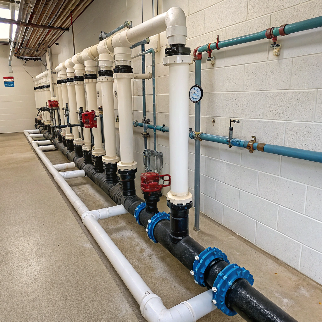
4. Use multiple inlets/outlets
If the plate is large, a single inlet may not be enough. Adding a second outlet or inlet can help even out the flow. Keep inlet and outlet positions symmetrical if possible.
5. Match pressure in all paths
All parallel paths must have the same resistance. That means equal length, number of bends, and cross-sectional area. If not, flow will favor the easier path.
| Parameter | Target Outcome |
|---|---|
| Equal path length | Balanced flow |
| Uniform channel width | Steady velocity |
| Short channel to surface | Low thermal resistance |
| Even spacing | No hot zones |
6. Simulate and test
Use simulation tools to check flow rates in each channel. After production, test a sample unit with thermocouples to make sure the heat is evenly removed.
Designing for uniformity means smoother operation, longer component life, and happier customers. It might cost more upfront, but the long-term benefits are real.
Using multiple parallel channels of equal length improves flow uniformity compared to a single long serpentine channel.True
Parallel channels can ensure more even flow distribution and shorter maximum path length hence better uniformity.
Minimising conduction path from heat source to the channel wall is irrelevant to flow uniformity.False
The distance influences how quickly heat reaches the coolant, hence affects surface temperature uniformity and cooling performance.
What are the latest trends in channel design?
I have been watching the state‑of‑the‑art designs and saw some exciting new patterns emerging in channel geometry and micro‑cooling.
Latest trends in channel design include micro‑channels and 3D jet‑channel layouts tailored to hotspots, topology‑optimised channel networks, gradually varied fin geometries, and additive/manufactured complex channels for extreme heat density applications.
Here are the trends I find most useful and promising:
Micro-channels
These are ultra-small channels that allow very high surface area contact. They’re used in electronics and data centers where heat flux is extremely high. They increase heat transfer but require precise manufacturing.
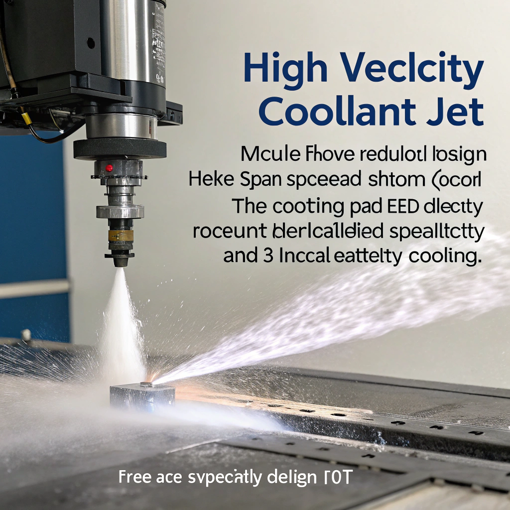
Jet impingement and 3D channels
These use a high-velocity coolant jet that hits the hottest spot directly before spreading. 3D designs reduce flow path length while maximizing local cooling.
Topology-optimized designs
Software tools now optimize channel layouts based on thermal performance goals. These tools adjust the width, shape, and number of channels to match the heat map of the surface.
Gradually varied fins
Instead of using uniform fins or straight grooves, engineers now use fins that change size along the channel. This allows better heat transfer near the inlet and better flow downstream.
Hybrid manufacturing
Complex channel shapes that can’t be extruded are now made by combining extrusion with machining, stamping, or 3D printing. This allows better performance without sacrificing manufacturability.
Better simulation tools
Simulation now includes digital twins and real-time data feedback. Designers test thermal, fluid, and structural models together. This makes it easier to balance cooling performance with cost.
These innovations help achieve better uniformity, reduce pump energy, and enable smaller, more effective plates. For a company working in aluminium extrusion and custom machining, keeping up with these trends means staying relevant and offering customers next-level performance.
Topology‑optimised channel layouts can reduce pressure drop while improving thermal performance compared to straight uniform channels.True
Studies show topology optimisation yields lower temperature rise or lower pressure drop than uniform straight channel layouts.
The trend in channel design is moving towards simpler, larger channels to reduce cost at all performance levels.False
Actually the trend is toward more complex, tailored, even micro‑channels for higher performance; cost reduction is part of manufacturability but not via simplifying channels alone.
Conclusion
Channel design is a critical lever in liquid cooling plate performance: by carefully choosing the layout, geometry and manufacturing approach you ensure uniform flow, low pressure drop and effective heat transfer. Uniformity matters as much as raw capacity. In your business you can differentiate by offering custom channel geometries, simulation‑backed designs and manufacturing tailored to both performance and cost.

