
How thick should a heat sink be for efficient heat dissipation?
A big, bulky heat sink doesn’t always mean better cooling—I’ve seen compact designs perform better just because the thickness and geometry were right.
The right thickness for a heat sink depends on base and fin roles: the base spreads heat from the source, and the fins transfer it to the air. Both need balance, not maximum size.
Let’s look at what determines the ideal thickness, why fin geometry matters, how to design efficiently, and what modern trends are shaping heat sink materials.
What determines optimal heat sink thickness?
Some heat sinks fail even if they’re huge—usually because their base is too thin or the fins are too close. I’ve run into this a few times when helping customers redesign.
The best thickness balances thermal conductivity, fin efficiency, base spreading resistance, airflow, and size limits. You can’t just make everything thick and expect it to work.
Here’s how I figure it out:
What to Consider
| Factor | Effect on Thickness |
|---|---|
| Base thickness | Helps spread heat across fin area |
| Fin thickness | Affects how well each fin conducts heat |
| Fin spacing | Controls airflow and surface area |
| Material type | Copper needs less thickness than aluminum |
| Airflow | Natural or forced convection changes design |
| Application limits | Size, weight, cost constraints matter |
A base that’s too thin can’t spread heat well. Fins that are too thin might not carry enough heat. But making everything thicker increases weight and cost, and can reduce airflow.
Typical Values
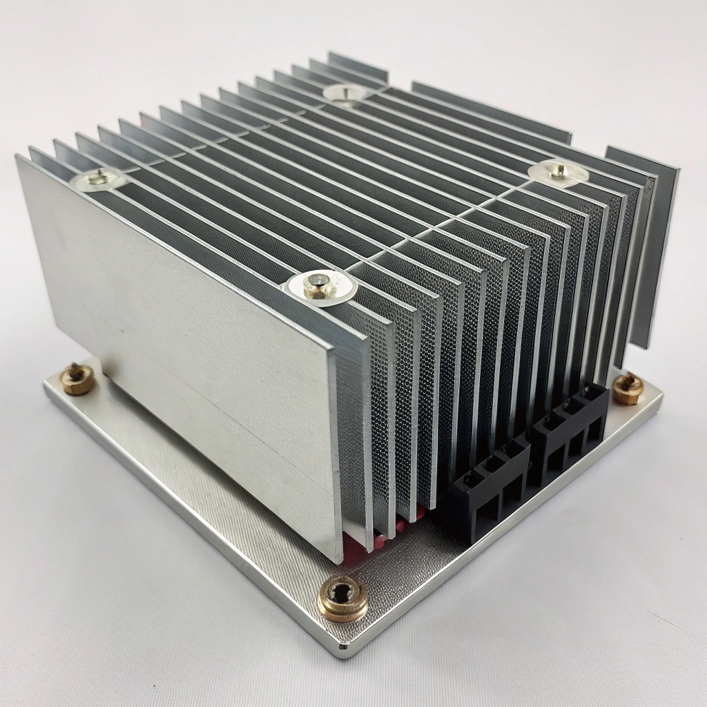
- Base thickness: Often 5–10 mm for extruded aluminum; more if copper.
- Fin thickness: Around 0.5–1.5 mm for aluminum; 0.2–0.6 mm for copper.
- Spacing: Usually >4 mm in natural convection designs.
- Fin height: Depends on airflow and design, but usually 20–50 mm.
The goal is to let heat flow from the source into the base, spread evenly, then move into the fins and out to air. If any part of that chain has high resistance, performance suffers.
Thicker base plates always give better heat sink performance.False
Only up to a point. After a certain thickness, more metal doesn't help because air cooling becomes the bottleneck.
Fin thickness affects conduction and airflow—both must be balanced for good performance.True
Fins that are too thin can’t carry heat well, and fins that are too thick block airflow.
What are the benefits of proper fin geometry?
I once saw a design fail thermal tests—not because the material was wrong, but because the fins were too close and blocked airflow. Changing fin spacing fixed it.
Well-designed fin geometry improves cooling by increasing surface area, allowing smooth airflow, and making each fin effective.
Why Geometry Matters
- Surface area: More area = better heat transfer, as long as air can move.
- Airflow: Air needs room between fins. Too close means poor cooling.
- Fin efficiency: Long, thin fins might not stay hot enough near the tips.
- Material use: Good geometry uses less metal for the same performance.
- Orientation: Vertical fins help with natural convection; cross-cut fins suit forced air.
Tips That Work
| Geometry Rule | Benefit |
|---|---|
| Fin spacing ≥ 4 mm | Avoids airflow blockage |
| Fin height < 45×thickness | Keeps manufacturing and cost realistic |
| Pin fins for forced air | Handles multi-directional flow |
| Flared fins for natural convection | Boosts vertical airflow |
I use these when guiding clients. It’s not about guessing—it’s about testing what shape lets heat and air flow together. That’s what gets real results.
Fin geometry is just for mechanical support and doesn’t affect heat sink performance.False
Fin spacing, shape, and thickness directly affect airflow, conduction, and convection.
Fins that are too close together can trap heat and reduce performance.True
Tight spacing limits airflow, creating hotspots and poor convection.
How can I design a heat sink with ideal thickness?
I always start with what problem we’re solving: how much heat, how fast, and where it goes. From there, I work backwards into dimensions and materials.
Designing the ideal thickness means understanding your power load, material limits, airflow, and size constraints. It’s a step-by-step balance, not guesswork.
Step-by-Step Plan
-
Define thermal goal
- Power load (W)
- Max allowed temperature rise (°C)
- Target thermal resistance (°C/W)
-
Pick material
- Aluminum for light, low-cost systems
- Copper for compact, high-performance sinks
-
Choose base thickness
- Thin if heat source is wide
- Thick if heat source is small and central
-
Select fin profile
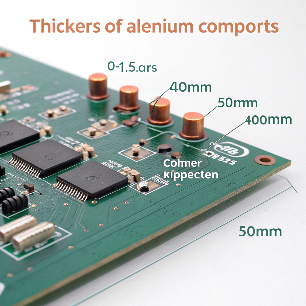
- Thickness: 0.5–1.5 mm (Al), 0.2–0.6 mm (Cu)
- Height: 20–50 mm
- Spacing: ≥4 mm (natural convection)
-
Simulate or calculate
- Use a calculator or CFD software
- Check base resistance + fin performance
-
Adjust and iterate
- Too hot? Thicker base or more fins
- Too heavy? Thinner base or shorter fins
Example Case
| Parameter | Value |
|---|---|
| Heat load | 50 W |
| Max temperature rise | 40 °C |
| Target resistance | 0.8 °C/W |
| Material | Aluminum 6063 |
| Base thickness | 8 mm |
| Fin thickness | 1.2 mm |
| Fin spacing | 5 mm |
| Result | Meets target with margin |
Heat sink design starts with thermal targets, not just dimensions.True
You can’t design the right thickness unless you know the heat load and temperature limits.
Thicker fins always improve heat sink performance.False
They might reduce the number of fins and surface area, which can hurt airflow and cooling.
What are the advancements in lightweight heat sinks?
These days, customers want smaller and lighter systems—especially for EVs, drones, and portable gear. That means we need better materials and smarter shapes.
New designs use thinner fins, mixed materials, and heat pipes to cut weight while still cooling power devices safely.

What’s Changing
-
Thin fin tech
- Skived fins let us make aluminum fins as thin as 0.3 mm
- More fins, better airflow, less metal
-
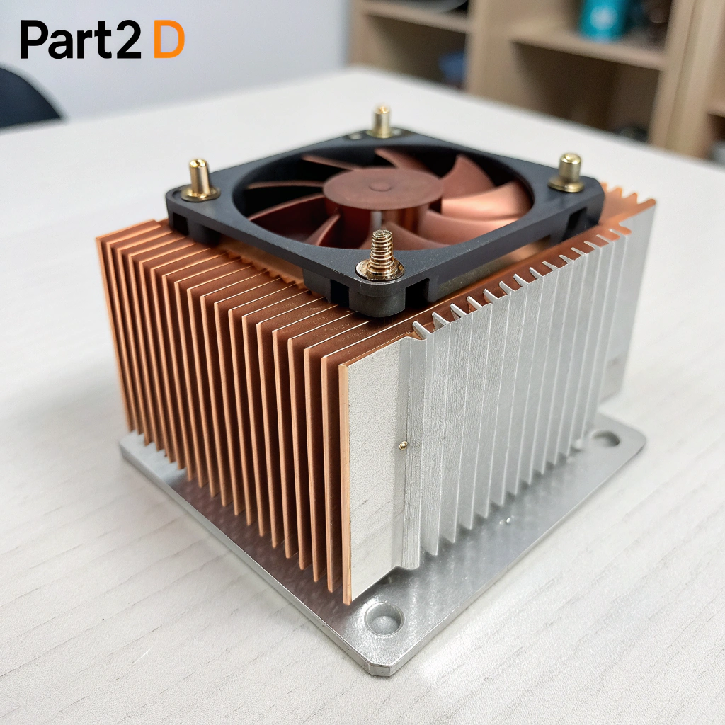
Hybrid designs
- Copper base + aluminum fins = better performance with less weight
- Common in high-end electronics
-
Heat pipes & vapor chambers
- Move heat fast with minimal metal
- Often replace thick bases
-
3D-printed structures
- Use lattice or honeycomb forms
- Strong, light, and custom-shaped
-
Surface coatings
- Black anodizing improves radiation
- Nano coatings reduce surface resistance
Summary Table
| Trend | Benefit |
|---|---|
| Skived aluminum fins | Thinner, lighter, better airflow |
| Vapor chambers | Spread heat with less bulk |
| Hybrid materials | Combine strength and cost |
| 3D-printed sinks | Less metal, custom fit |
| High-emissivity coatings | Boost passive cooling |
We now offer thinner custom profiles, lighter aluminum alloys, and finishes that boost thermal output. It’s not just about shape anymore—it’s about total system efficiency.
Lightweight heat sinks often use skived fins or vapor chambers to reduce size and mass.True
These methods provide high surface area and fast heat spreading with less material.
Thicker heat sinks are always better than lighter ones, regardless of application.False
Thicker designs may be heavier, bulkier, and less efficient in modern systems.
Conclusion
Choosing the right heat sink thickness means matching your thermal needs with the right material, shape, and airflow. Too thick wastes space and weight. Too thin risks overheating. With new materials and smarter designs, it’s now possible to cool high-power electronics more efficiently and more compactly than ever before.

